|
Turbocharger-Intercooler-Bypass Valve, Technical Tips, 1986-90 5000/200TQ Audi Turbo Compressor Maps Boost Problems: 10V Turbo Engine The ABC's of Running High Boost:
Boost Problems: 20V Turbo Engine,
MC Turbo Engine,
20V Single Pass Intercooler Installation in 10V Turbo engine
The Water Cooled Audi Turbo
Beginning in the 1985 Model Year, the Audi 5000T with 2.1 liter 5 cylinder engine came with a water cooled turbo and after-run system which incorporated a electric coolant pump which would circulate water through the turbo after the engine has shut down.
According to the Audi Service Training publication entitled '1985 Model Change Information'(1),
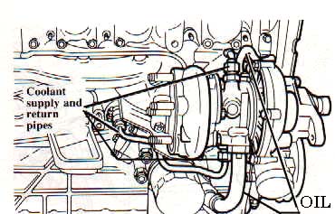
"The Audi 5000S Turbo now features a water cooled turbocharger housing. The new turbocharger housing has an internal water jacket cast around the area of the exhaust turbine. Engine coolant flows at an average rate of about 6 liters a minute during engine operation."
"The circulating engine coolant draws heat away from the exhaust side of the turbocharger housing and reduces the temperature of the unit,. The lower temperatures help prevent carbonization of engine oil in the turbocharger. The water cooling also keeps the turbocharger operating temperature at more uniform levels during changing engine loads."
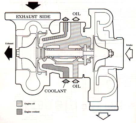
Here is a cross section diagram showing the water and oil passages
through the turbo.
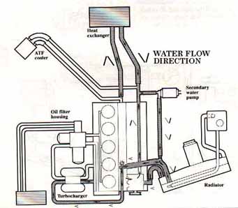
"The secondary coolant pump is operated by an electric motor. The small water pump is connected between the radiator supply hose and the heat exchanger return hose. The water pump is located on a bracket below the brake master cylinder. The system will only operate when the engine is shut off." " The coolant pump is operated by a thermo-switch which activates a control relay. The thermo-switch is located in the coolant output flange on the cylinder head. The thermo-switch closes at 110C and opens at 90C. When the thermo-switch closes, it supplies the control relay with power. The control relay activates the secondary coolant pump and the radiator fan on 1st speed."
"The control relay also operates the coolant pump for five seconds after the car has been shut off for more than one hour and is then restarted. This is done to lubricate the pump seals over an extended period of inoperation." WARM UP/COOL DOWN THE TURBO
It is a good idea to avoid high boost initially after starting a cold engine until the oil temp gets up to 60C (this is recommended in the factory operators manual)
If you ever need a reminder to let your engine idle to cool down after a high boost driving session, just open up your hood at night and check out the red hot exhaust manifold and turbo! Even with the water cooled turbo you should let the car idle for several minutes. It may take 10-15 minutes of normal low boost driving before the exhaust manifold/turbo cool down. Turbo Compressor Nut come loose? My 87 5000TQ track car with the 5 cylinder 10V MC turbo engine, normally runs about 2.15 bar (~16 psi) of boost with a MAC11C ECU which uses a 2.5 bar pressure sensor. The other day while entertaining the BMW folks at the Portland International Raceway (PIR) during a BMW car club day, my Waste Gate diaphragm tore open and the turbo boost climbed up to the overboost cutout, which I had set a "little" high at 2.45 bar, (~21psi).
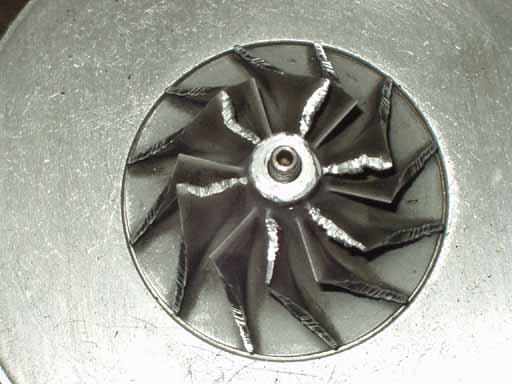
The engine cutout briefly as I streaked down the front straight, and apparently the stock K26 turbo compressor nut thought it would be a good time to spin off and roll around in front of the compressor wheel.
I limped off the track while creating a pretty good smoke screen which did entertain the BMW folks that day. When I removed the turbo intake boot and metal pipe, I found the nut and the two washers had gotten up in the CIS intake boot area. I also had some aluminum shavings that had been blown into the intercooler which needed to be cleaned out.
SJM Autotechnik™ : BOOST BYPASS VALVE
The Turbo Bypass valve from the 1991 200TQ 20V engine can be installed on the 10V Turbo engine to allow air to recirculate around between the turbo intake and outlet during gear shifting to reduce turbo lag. Plumbing in the valve requires a little fabrication as you need to connect the bypass valve into the metal Turbo inlet pipe and into the Turbo exit hose. You can also connect into the intercooler inlet or outlet instead of the turbo exit hose.
Some people cut out a section of the metal Turbo intake pipe and insert a tee with rubber collars to connect the low pressure side of the bypass valve, and others weld a 1 inch hose fitting onto the metal pipe directly. The intercooler on some 1986-88 5000T/Q's have a rubber cap over a port in the center between the inlet and outlet hoses. This smaller fitting is connected into the intercooler inlet (Turbo exit) and can be used to connect the boost end of the Bypass Valve into the system.
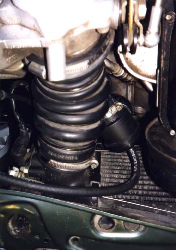
On my 89 200TQ 10V, I installed the 20V intercooler so I was able to use the 20V Turbo exit hose with built in hose for the bypass valve. Here is a photo showing the location I used. Some have installed the bypass valve behind the right side headlamp area where more area may be available.
I had a 1 inch fitting welded to the metal Turbo intake pipe and located the valve next to the intercooler exit hose. Things are very tight in this installation and a heat shield was installed to protect the bypass valve from getting toasted from the exhaust manifold heat. If I had to do this over again, it may make more sense to use the original turbo exit hose, and cut it in half, and install a custom made Tee fitting with the 1 inch bypass hose connection, and use some 1" hose to locate the bypass valve up behind the headlamp area.
Samco used to make a silicone intercooler exit hose that had an extra fitting to allow connecting a bypass valve as well. Fitting the Samco hose to the oval shaped throttle intake can be challenging.
The small hose fitting connected to the Bypass valve is normally connected to the intake manifold to get vacuum and boost pressure to allow it to operate correctly. The hose from the intake manifold provides engine vacuum to open the valve during gear shifting (throttle closed) which allows the turbo to continue to spin and reduce turbo lag when you get back on the throttle.
It is important to understand that the Bypass valve will also be open when the engine is idling when no boost is produced.
The other important thing to understand is:
THE TURBO BYPASS VALVE REQUIRES BOOST FROM THE INTAKE MANIFOLD CONNECTED TO THIS SMALL FITTING ON THE BYPASS VALVE, TO HOLD IT CLOSED AS THE TURBO PRODUCES INCREASING BOOST.
On the 10V Turbo engines in the 1986-90 5000TQ/200TQ when connecting a hose to the Bypass Valve small fitting:
DO NOT USE THE SMALL VACUUM PORT ON THE INTAKE MANIFOLD NEAR/BELOW THE THROTTLE VALVE TO GET INTAKE MANIFOLD VACUUM/BOOST.
THIS FITTING HAS PORTED VACUUM THAT CHANGES WITH THROTTLE OPENING AND WON'T WORK.
DO NOT USE THE SMALL FITTING AT THE IDLE STABILIZER VALVE HOSE CONNECTION EITHER, AS THIS CONNECTION GOES IN FRONT OF THE THROTTLE VALVE, AND DOES NOT HAVE INTAKE MANIFOLD VACUUM.
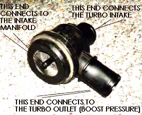
Both of the large hose connections on the Bypass valve must be connected, one to the turbo intake (low pressure) and one to the turbo exit (High pressure) as shown below.
If you leave the low pressure side open as in a dump valve installation, the valve will be open at idle and will create a false air leak that the fuel systems CIS Air Flow unit will not measure.
The Turbo Bypass valve often leaks due to a torn internal diaphragm. You can use a hand vacuum pump to apply vacuum to the small hose fitting and check for correct operation and see if the valve is leaking.
If the diaphragm is leaking, you may lose boost pressure as the valve relies on the internal spring and boost pressure to hold the diaphragm closed.
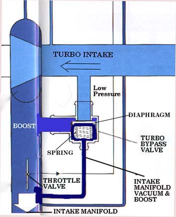
Here is a diagram of the valve installation showing the correct orientation of the connections to both the boost side and the turbo intake side.
Diagram courtesy of Audi of America
Waste Gate Testing Info can be found on the following page. Waste Gate
MC Turbo Engine, early 89 200TQ vs Late 1989 200TQ, Single and Dual knock sensor MC engines
There were some mid-89 model year changes made to the "MC" designated engine for the 200TQ cars. Keep in mind that the actual "production" dates (shown on the driver's side pillar) for the 89 model year cars start around 6/88. I recently bought an "89" 200TQ that has the later MC engine with dual knock sensors, smaller turbo, different computer (MAC 14), different camshaft etc. that has a production date of 12/88. The change to the dual knock sensor engine with above changes occurred in 11/88 at VIN # 44KN038268.
One way to tell the earlier and later engines apart is to look on the firewall where the connectors are mounted for the knock sensor(s), and the two crank/flywheel sensors. The later model MC engine will have 4 connectors versus the 3 connectors on the earlier MC with the single knock sensor connection. (Note: This applies to the US version MC with O2 sensor) You can also look for the second knock sensor mounted toward the rear of the engine block.
The factory training service book (89 Model year changes) indicates that the engine has more low end torque but the same HP output.
20V Intercooler installation into 10V engine
The Single Pass intercooler (Audi Part # 034-145-805 G, list price $348) from the 1991 200TQ 20V can be fitted to the earlier 10V engines. It has the same width and height as the dual pass 5KTQ intercooler, but uses a core that is 1.75 inches longer. The Single Pass 20V Intercooler will have less pressure drop thorough the intercooler and provides a performance upgrade with the same amount of boost pressure. With the exception of the fabrication required to connect the turbo exit hose to the larger 70mm intercooler inlet pipe, for the most part, it is a bolt on affair. Coming up with a solution for the connection between the turbo exit hose 58mm ID and the 70mm OD metal intercooler inlet pipe does take a bit of fabrication work. Ideally, you want this connection to have a smooth tapered transition between the turbo exit and the intercooler inlet.
The 20V intercooler has the intake temp sensor boss cast into the plastic end cap like on the 10V intercooler, but the 20V intercooler temp sensor boss needs to be drilled and tapped for mounting the 10V air temp sensor. I used 6mm studs in the intercooler boss with some loctite to mount this temp sensor.
The existing sheet metal body cross piece with the front engine mount located between the bumper mounts, needs to be removed on the 10V vehicle. There are two spot welded areas that need to be cut loose from the upper core support piece when removing this cross piece.
This original metal cross piece prevents the 20V intercooler Inlet pipe from coming straight up from the bottom and into the single pass intercooler. Remove the bumper assembly and the bumper shock absorbers and as mentioned, cut loose the two spot welds holding this cross piece on.
The 20V vehicle uses a metal cross bar (Audi Part # 447-805-851A, list price $399) which bolts on behind the bumper shock absorbers. This bar has a welded on bracket for the front engine mount and has some bracket mounting tabs for holding up the intercooler Inlet pipe. The 20V cross bar is bent forward and is routed in front of the intercooler mounting to allow the Single Pass Intercooler Inlet Pipe to come straight up from the bottom.
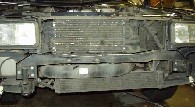
Here is a photo showing the intercooler installation in a stock 1991 200TQ 20V.
The 20V uses a 70mm Inlet pipe (Audi Part #034-145-731, list price $290), which may have to be cut in the middle and then rotated down to better aim at the Turbo exit hose. A piece of 70mm (2.75 inch) high pressure silicone hose should be used to couple the two pieces of the metal pipe.
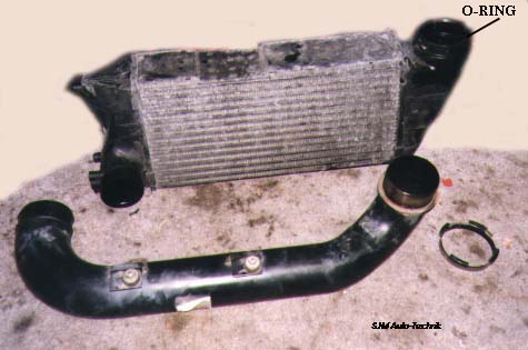
Here is a photo of the 20V Intercooler and Inlet Pipe.
The 20V turbo exit hose (Audi Part # 034-145-746 N, list price $235) was used for the connection from the 50mm K24 turbo exit pipe to the 70mm Inlet pipe. This 20V Turbo exit hose has an extra rubber hose grafted on for fitting the Turbo bypass valve but the location of the bypass valve is a bit tight.
An alternative to using the expensive 20V turbo exit hose, would be to have a tapered metal adapter pipe made which would match the 58mm turbo exit hose ID opening and the 70mm OD Intercooler Inlet metal pipe. A short piece of 70mm high pressure silicone hose could be used to connect this tapered adapter to the 70mm inlet pipe. You could also have the 20V metal 70mm OD inlet pipe modified by someone skilled in TIG welding. They could cut and weld the 70mm inlet pipe to allow a tapered adapter to be grafted onto the end of the 70mm pipe to allow the OEM 10V turbo exit hose with a 58mm ID to connect directly. The K24 turbo cold side housing may also need to be rotated slightly for better alignment of the turbo exit connection.
The intercooler Inlet Pipe connection uses an O-ring (Audi Part # N 904-324-01), and special clamp pieces (Audi Part # 034-145-813 B, 2 pieces needed) and a hose clamp where this Inlet pipe is connected to the Intercooler. The factory parts should be used here. The best way to do this conversion, as I did, was to get all the parts from a donor car, as these parts can be very expensive when purchased separately from the Audi Dealer.
(1) Audi Service Training Publication. '1985 Model Change Information'
Copyright © 1998 - 2010 SJM Autotechnik™ , all rights reserved. Return to Troubleshooting Tips page. Return to SJM Autotechnik™ main page.
|
| About Us Privacy Policy Terms of Use Links Customer Service Safety Information Home |