
|
ECU System, Waste Gate System Operation, 1986-90 5000/200TQ:
Digital Boost Control System (Hitachi MAC-11/12/13 ECU's The following is an excerpt from the Audi Service Publication "1986 Model Change Information" . One section in this publication, details the operation of the 2.22 litre, "MC" designated 10V Turbo engine. Unfortunately, this publication is no longer available from Audi USA. Note: The later Dual Knock sensor MC engine, with MAC-14 ECU, uses a similar boost control system. "DIGITAL BOOST CONTROL" "The boost pressure from the turbocharger is now electronically controlled. A specified manifold pressure map is programmed into the engine control unit. The control unit operates a frequency valve which regulates the operating pressure in the upper chamber of the turbocharger wastegate, thereby controlling boost pressure." "The system is activated by the full throttle switch, which closes when the throttle is opened more than 57 degrees ( about 2/3 throttle). The control unit will then operate the wastegate frequency valve to reach and maintain the specified manifold boost pressure. The objective of the system is that the cylinders are always filled with the same amount of boost pressure during turbocharger boost conditions, regardless of intake air temperature or atmospheric air pressure." "This gives the following benefits:
"The manifold pressure map is programmed into the control units's memory in relation to engine speed. The map is calculated to match the flow characteristics of the intake tract and intake manifold at different engine speeds. The system provides maximum low RPM boost pressure for high engine torque and good throttle response. Boost pressure is gradually lowered at higher engine speeds to reduce the possibility of detonation. When driving at part throttle, boost pressure is maintained at a lower level via conventional wastegate operation. This reduces engine pumping losses and improves fuel economy. The values in the control unit's memory for the manifold pressure map are also corrected for changes in temperature of the intake air. In this manner the system will compensate for variations in air density caused by temperature fluctuations. This ensures a uniform amount of boost pressure to the engine regardless of temperature. At higher altitudes air pressure decreases. The absolute boost pressure via conventional wastegate operation will also decrease. The digital boost control will once again compensate for this by maintaining the absolute boost pressure at the predetermined level of the manifold pressure map regardless of altitude. This results in the engine having the same power output at all altitudes and barometric pressures. " The following diagram, shows the boost pressure produced, with and without the digital boost control system. 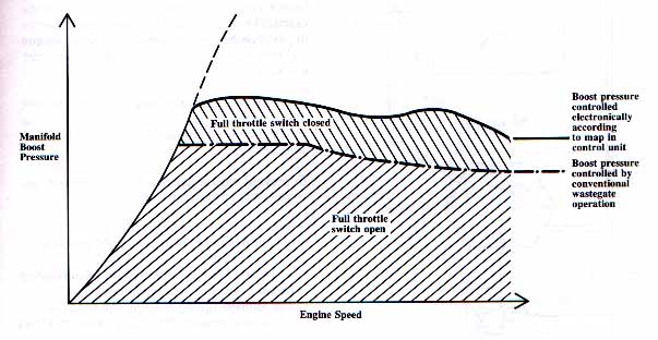 Diagram courtesy of Audi of America, Technical Service Training Booklet "WASTE GATE FREQUENCY VALVE" "The wastegate frequency valve is located next to the ignition coil assembly. It is operated by the engine control unit and regulates the operation of the turbocharger wastegate. It does this by switching the vent line from the upper chamber of the waste gate between the connection to the intake air boot (which is at approximately atmospheric pressure) and the connection to the intake manifold (which is subject to manifold boost pressure). At a duty cycle of 0% the vent line is connected only to the intake air boost. Boost pressure will now be determined conventionally by manifold boost pressure in the lower chamber of the wastegate and spring pressure in the upper chamber. At a duty cycle of 50% the upper chamber of the wastegate will be connected equally to both the intake manifold and intake air boot. Part of the manifold boost pressure will now pressurize the upper chamber of the wastegate. The wastegate will now stay closed longer and boost pressure will be raised. By controlling the frequency valve's duty cycle, the control unit can regulate boost pressure to match the predetermined value in the control unit memory. To prevent engine damage from overboost, the system will not operate when:
The following diagram shows the connections from the waste gate frequency valve to the waste gate. 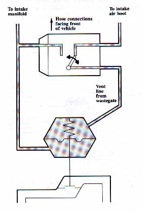 Diagram courtesy of Audi of America, Technical Service Training Booklet SAE Technical Paper #8601013 "The Third Generation Turbocharged Engine for the Audi 5000CS and 5000CS Quattro" This is a great technical paper presented by the Society of Automobile Engineers (SAE) on the design and operation of the "MC" 10 Valve Turbo engine first used in 1986 Audi 5000CS Quattro. This paper was written in 1986 by D. Stuck of Audi AG, Neckarsulm Germany, and it contains detailed information not found anywhere else on the operation of this great engine. It can be ordered from SAE by visiting their web site, or by calling them directly. Here is the link to their web site SAE Technical Papers. A listing of other great SAE papers on Audis and other automotive technical topics, can be found at SAE Paper Listing WASTE GATE CONTROLS- ECU and WG SOLENOID HOSES The larger lower Waste Gate (WG) control hose should be checked for cracks or restrictions as a leaky or restricted hose can cause overboost conditions which will force the ECU to shut off the fuelpump. If you have low boost pressure and suspect a problem with the turbo, or with the exhaust system being clogged, you can pinch off this lower Waste Gate hose, and see if you hit the overboost fuel pump cutout when driving at WOT. This is one quick test for the turbo, but keep in mind that any leaks in the turbo hoses may prevent the boost pressure in the manifold from rising, and may overspin the turbo during this test. A leaky WG diaphragm will also cause overboost problems. See below for leak testing the WG diaphragm. The upper Waste Gate hose should be checked to make sure it is connected to the Waste Gate Solenoid correctly as well as checking the other two hoses that are connected to the Waste Gate Solenoid. The top hose in the center of the Waste Gate Solenoid should be routed to a small fitting that is inserted into the turbo intake boot. The other top (outer) Waste Gate Solenoid hose should be connected to the top of the Waste Gate Cap fitting. The bottom Waste Gate Solenoid hose should be connected to the intake manifold to get boost pressure. Note: On the 5 speed manual transmission vehicles, this lower Waste Gate Solenoid hose is typically routed over to the deceleration valve (behind the passenger side fender) where it is teed to the hose from the intake manifold. In the Automatic Transmission Turbo vehicles, this lower hose normally goes directly from the intake manifold fitting to the lower fitting on the Waste Gate Solenoid. Some vehicles may have slightly different routing of this manifold hose depending on whether the GH recall campaign was done. If the GH campaign was completed on the 1986-89 5000/200TQ, there should be a sticker under the hood showing the vacuum routing diagram, part number 034-010-102L. Originally, before the GH campaign is performed, the small hose from lower fitting on the Waste Gate Solenoid, was connected to a different single port on the rear portion of the intake manifold that also connects to the idle stabilizer hoses. This port receives pre-throttled air from an internal pipe in the intake manifold. In some cases the two hoses from the intake manifold and the turbo inlet that connect to the top and bottom fittings on the WG solenoid can be reversed and this can cause overboost conditions. Here is a photo showing the Waste Gate Solenoid Connections. 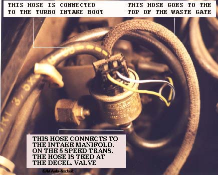 CHECK HOSES FOR VACUUM/BOOST LEAKS You can also use a hand vacuum pump to check for vacuum leaks on the two small rubber hoses coming from the rear of the intake manifold distribution pipe. One hose provides manifold vacuum/pressure to the waste gate solenoid and one hose connects to the Engine Control Unit (ECU). The slightly larger hose connects to the ECU on two vehicles I checked. You can find out if you are connected to the hose going to the ECU, by turning the ignition on and viewing the dash boost gauge when you apply vacuum to the hose under question. You should see the dash boost gauge read ~0.3 bar when you apply 20 inches of vacuum. Both of these hoses should hold vacuum and not leak. Here is a picture of the two hoses in question. 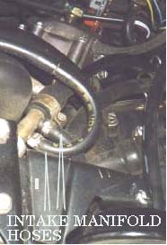 WASTE GATE SOLENOID TESTS: The waste gate solenoid system and hose can also be tested by using a self test the ECU performs with the engine idling. Connect a vacuum gauge to the hose coming from the waste gate solenoid that connects to the upper waste gate chamber. Unplug the throttle switch connector and use a small wire jumper to briefly short across the two lower connector pins (Full throttle portion of the switch), the ECU will then cycle the waste gate solenoid on and off rapidly for a few seconds after connecting the jumper wire. You can place your hand on the waste gate solenoid to feel the solenoid operate during this brief cycling test. During this cycling test, the vacuum gauge needle should swing back and forth indicating that the hose from the intake manifold to the waste gate solenoid, and then to the waste gate upper chamber is ok, along with the waste gate solenoid operation. This test indicates that the Waste Gate solenoid is correctly mixing intake manifold vacuum and air at atmospheric pressure coming from the turbo intake boot. If the vacuum gauge needle does not move, you could have a leaky waste gate diaphragm. See below for leak testing this diaphragm. The section on the Multifunction Temp sensor should be reviewed if this test does not work as the waste gate solenoid will not function if this Multifunction temp sensor is indicating a false overheat condition. Go to the section above to check the operation of this sensor to ensure it is not causing the low boost problem by preventing the correct operation of the waste gate solenoid system. PRESSURE TEST THE WG SYSTEM and ECU HOSES You can do a pressure test of the Waste Gate Solenoid and ECU hoses shown above by pressurizing the small intake manifold hoses with ~14.5psi gauge pressure. (2.0 bar absolute pressure) You can first check the hose to the ECU by pressurizing one of the hoses and then watching the dash boost gauge readout. If the readout does not go up, try pressurizing the other hose. Avoid applying much more than 14.5 psi gauge pressure (2.0 bar absolute pressure) to the ECU hose to avoid damaging the ECU's internal pressure sensor. After checking the ECU hose, you can then pressurize the other small intake hose and then run the ECU OUTPUT test to cycle the Waste Gate Solenoid on and off. Go to the ECU FAULT CODE and OUTPUT TEST SYSTEM page for more details if you have never run the ECU Output tests. To run the Output Tests: Basically you insert a fuse into the fuel pump relay, then turn on the ignition, remove the fuse and then insert for 4 seconds, the CIS freq valve will start to oscillate, now remove the fuse again and insert for 4 seconds, the Waste Gate Solenoid should now be cycling on and off once per second. While you are running the output test on the WG solenoid, you can remove the small intake manifold pressure hose listed above for the Waste Gate Solenoid and apply pressure (~14.5psi gauge pressure, 2.0 bar absolute pressure) to the waste gate solenoid lower hose using an air compressor and regulator. Then use a tee fitting to connect a pressure gauge to the hose that connects from the top of the waste gate chamber to the top of the WG solenoid. While the OUTPUT TEST is happening, and the Waste Gate Solenoid is being cycled on and off, you should see the pressure gauge needle swing up and down once per second. Normally, the pressure gauge needle will swing up to within 1 or 2 psi of the pressure used to test the system. In other words, if you are applying 14.5 psi to the WG solenoid lower inlet, the pressure gauge connected to the top of the waste gate should swing up to ~13-14psi during the output test. This test will verify that pressure is being added by the waste gate solenoid to the top of the Waste Gate. I have run across a few WG solenoids that leak slightly and don't apply full pressure to the top of the waste gate. If the pressure gauge needle does not move at all, remove the lower hose on the bottom of the waste gate solenoid and see if the pressure is making it to the solenoid. If that hose is ok and the solenoid is clicking on and off, then remove the hose going to the top of the waste gate diaphragm and plug it. If you now see the pressure gauge needle move back and forth, the waste gate diaphragm is likely leaking. LEAK TEST THE WASTE GATE DIAPHRAGM You can also use a hand vacuum pump to test the waste gate diaphragm for leaks. Connect the hand pump to the top waste gate chamber port and pump it down to about 15-20in vacuum. The waste gate upper chamber should hold vacuum. If it is holding vacuum, you can quickly remove the hose and you "may" hear the waste gate valve "CLUNK" back down to verify the waste gate is not stuck. The waste gate valve normally moves about 15mm when it is fully open. Go to the Waste Gate Spring Installation page for details on inspecting the WG diaphragm if you suspect you have a leak. In the US, back in the good old days, the Audi dealer only listed the complete waste gate assembly available for repairing a leaky waste gate diaphragm at a cost of over $900, but these diaphragms used to be available separately many many years ago..... You can also use this pressure gauge to check the pressure added to the top of the Waste Gate chamber while driving the car at wide open throttle with the engine warmed up. With a stock ECU for the MC engines, approximately 2-3 psi will be added depending on altitude and condition of the waste gate spring. With a modified ECU (1.8 bar, 11.6psi), and using a stock Waste Gate spring, approximately 8 psi will be applied to the upper waste gate chamber. This test was done in 4th gear, WOT at ~3500 RPM using a 1988 5000TQ with the MC single knock sensor engine. NOTE: If the Waste Gate Solenoid system is working and you are seeing pressure being added to the top of the WG chamber, but the pressure added is lower than expected, double check the air temp sensor wiring connections and check again for stored fault codes. One vehicle I tested with a modified (1.8 bar) ECU and a stock Waste Gate spring, had a functional Waste Gate Solenoid system but would not make more than 1.4 bar boost. The WG solenoid was only adding ~4 psi to the top of the Waste Gate chamber. I found some intermittent wiring connections at the air temp sensor and the ECU was limiting the boost. NOTE: If by some strange occurrence the idle switch contacts or the wiring to the throttle switch are shorted, the ECU won't allow correct waste gate solenoid operation when you are at Wide Open Throttle (WOT). Remember to use an assistant to view the pressure gauge while driving the car. LED TEST LIGHT FOR WASTE GATE SOLENOID A LED test light can also be connected across the two WG Solenoid connections to visually see how the waste gate solenoid is cycled on and off while performing the ECU self test. You can also view the operation of the waste gate solenoid with the LED connected across the Waste Gate solenoid while driving the car under boost. The LED can be placed near the windshield to view during a test drive to see if the ECU is attempting to adjust the boost using this solenoid. Use an assistant to drive the car while you watch the LED flickering on/off. This test works best at night as sunlight can wash out the LED. Basically, the LED with series resistor is connected in parallel across both Waste Gate terminals. This LED setup is similar to the US 1115 test light used in the Bentley. If you get two female and two male crimp connectors like the original bullet shaped connectors you can make a little harness that has two wires that plug onto to the Waste Gate solenoid and two that plug into the original two pin wiring connector along with the LED connected across these two terminals. The LED normally needs a 500-1k ohm resistor in series to limit the current, most LED's operate with 10-30milli amps. The lower the resistance the brighter the LED, up until the point the smoke gets out. There are some newer "Super bright" LED's that work great. I normally use two different colored wires similar to the original solenoid wiring, green/yellow stripe is the ground provided by the ECU (varying duty cycle) and blue/black stripe which is the steady +12V. The LED is polarity sensitive. It won't hurt it if you connect it backwards, it just won't make no light.....the resistor can be connected in series on either the + or - wire to the LED. Some have suggested using two LED's connected with opposite polarity in parallel so the test light won't be polarity sensitive as is used in the latest version of the VAG 1115 test light, but I have found the single LED works better when testing the Waste Gate solenoid. This is because with the two LED setup both LED's will light up from the inductive kick when the ECU cycles the solenoid on/off and you can't really tell if the duty cycle is correct by watching the brightness of the two LED's. Normally the LED will flash on and off brighter as you first enter Wide Open Throttle (WOT), then the LED brightness will fade some at higher RPM. If the LED stops blinking completely at higher RPM's while at WOT, it indicates the WG Spring tension is high enough to produce the required boost value that is mapped out in the ECU. OVER BOOST PROBLEMS: The large main hose coming from the back of the intake manifold and connected to the lower chamber of the WG delivers pre-throttle boost pressure from the intercooler exit to open the Waste Gate. Leaks in this hose can cause overboost conditions! There is a passage way that is cast inside the intake manifold that provides this pre-throttle boost pressure. If you remove the accordion hose and look inside the throttle area, you can see this port. The idle stabilizer also uses this port to provide air around the throttle plate to adjust the idle speed. The internal WG diaphragm can also develop leaks and may prevent correct operation of the WG. You can apply vacuum to the upper waste gate chamber using a hand vacuum pump to check the diaphragm for leaks. It should hold 15-20in of vacuum. Go to the Waste Gate Spring Installation page for details on inspecting the WG diaphragm The WG valve should also be checked for free movement and in some cases can stick partially open or closed preventing correct boost pressure. The line that connects from the turbo intake boot to the top (Center) fitting on the Waste Gate Solenoid must not be kinked or restricted, or this could cause overboost problems. The Waste Gate Solenoid relies on this line to vent pressure that is applied to the top of the Waste Gate Diaphragm. TURBO BOOST REFERENCE CHART - STOCK ECU The 89-90 200TQ and the 89-91 200T with the dual knock sensor MC engines with higher compression (8:4 to 1) that use the MAC14 ECU do have a boost control map with slightly lower boost settings when compared to earlier MC single knock sensor engine (7:8 to 1) with the MAC11 ECU. Here are the following values used in the MAC14: RPM 2000 2975 4000 5000 5325 5575 6000 6375 Boost map value 1.36 1.38 1.37 1.375 1.39 1.39 1.38 1.37 The MAC11 uses these values: RPM 1000 2000 3000 4000 5000 5500 6000 6375 Boost map value 1.04 1.35 1.4 1.4 1.4 1.42 1.4 1.4 HIGHER BOOST CONTROL FOR MAC11 AND MAC14 ECU'S At first, I modified my 89 200TQ with a reprogrammed EPROM that allowed a higher overboost fuel pump cutoff (1.95 bar) that kept the factory rev limit intact. This was done by increasing the overboost cutoff map values. With this change the boost was controlled almost entirely by the stiffer waste gate spring with a little assist (briefly) from the computer adding pressure on top of the Waste Gate. The next step was to change the actual boost map to have the ECU set the boost to 1.8 bar. This allows the ECU to give some momentary overboost when using a waste spring with about 1.7 bar. At higher altitudes one needs to be cautious as the Mac11 and Mac14 ECU's have no altitude (barometric) sensors which are used in the 91 200TQ and on the S4/S6 20V engines to lower the boost at higher altitudes and prevent the turbo impeller from over-revving. Fuel Pump Cutout at 3000 RPM with Brakes On? Automatic Transmission ECU wiring The Automatic Transmission vehicles with the MC engine and the MAC10/11 ECU have a "slightly" different wiring harness for the ECU. Pin 6 on the ECU connector will have a wire connected to this terminal that is grounded. This tells the ECU that a vehicle with an automatic transmission is fitted and the ECU will cut the fuel pump relay on and off at ~3000 RPM if you apply the brakes and give the engine full throttle. If you install this harness into another vehicle with a manual transmission, you should cut this wire going to Pin 6. REV LIMITER, OVERBOOST CUTOUT, 5000TQ/200TQ The later MC dual knock sensor engine and MAC14 ECU stores fault code 2214 if the maximum RPM (6700) is exceeded. It also has code 2224 which indicates the maximum boost pressure (approx 1.6 bar) has been exceeded. If you raise the overboost cutout values inside the ECU EPROM to 1.95 then this limit for code 2224 is raised as well. The MAC11 ECU uses the same Rev limit at 6700 and overboost cutout at 1.6 bar but the ECU does not store the code for exceeding these values. NOTE: The stock dash mounted Tachometer is sometimes not very accurate at the higher Rev values, I have seen the Rev limit occur at 7100 RPM as displayed on the dash gauge, even though an accurate tachometer shows the rev limit occurring at the prescribed 6700 RPM value. Return to ECU System Technical Tips Copyright © SJM Autotechnik™ , all rights reserved Return to Troubleshooting Tips page. Return to SJM Autotechnik™ main page. |
| About Us Privacy Policy Terms of Use Links Customer Service Safety Information Home |