|
Electrical System,Technical Tips, 1986-88 Audi 5000 Turbo/Quattro, 1989-91 Audi 100, 200 Turbo/Quattro 1992-95 100/S4/S6 (some information applicable)
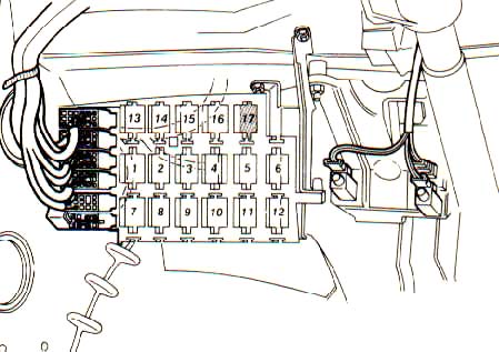
ABS Light On, ABS Relay Fuse Blown? The 1986 and later Audi 5000/100/200/S4's with Antilock Brake Systems (ABS) have a dedicated ABS relay which uses a fuse that is located in the top of the relay. The relay is usually located under the dash, on the drivers side (LHD vehicles) in the Aux relay panel. Always check this ABS fuse first, if you are having ABS issues. Accessing the aux relay panel for the 1989-91 Audi 100/200 is shown here.
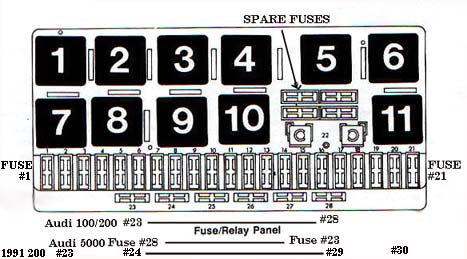
Basic Electrical Checks: Main Fuse and Relay Locations
Here is the fuse and relay locations, as found under the front hood, near the windshield on the Audi 5000/200.
Note: The locations of fuses #23 to #28 are reversed on the 1986-88 Audi 5000 when compared to the 1989-90 Audi 100/200.
The 1991 Audi 200/TQ has additional fuses #29 and #30.
Several other relays are mounted on the auxiliary relay panel under the dash on the 5000/200TQ. The Audi 5000's have a small cover on the lower dash area that often has a diagram showing the specific relay locations. You may want to use caution with these diagrams, as I have found a few that were incorrect. Often you will want to check the relay part number or the specific wiring details at the relay to ensure you have the correct relay. You can remove the lower dash cover panel(s) on the Audi 5000's to get a better look at the relays, this requiring only a Phillips screwdriver and flash light to locate the screws.
Auxiliary Relay Panel Under Dashboard
Normally, on the later 1989-91 200TQ's with drivers side air bag and knee bar, the knee bar needs to be removed to get at the auxiliary relay panel. This is a bit of a pain, but can be done without too much screaming. The side dash panel (cover) needs to be removed first, to allow you to get at two of the screws that secure the knee bar to the aluminum dash support. There is usually one lower hex head screw securing this side panel cover, and after the removal of the screw, then the side panel is pulled down slightly, and then up and out. It does not come out or go in very easily.
After you get the side panel cover out, there are two hex head screws visible behind the cover holding the knee bar to the dash support. There there are a few other allen head screws underneath the knee bar that need to be removed to allow the knee bar to come down and out. See, that wasn't so bad, now was it!
The knee bar will often have a stick on the back showing the location of the relays in the aux panel, but once again these diagrams are not always correct due to last minute production changes. The aux relay locations detailed in the Bentley manual also don't match up with what I found in my car.
AUX RELAY LOCATION: 1989 Audi 200TQ
On my late 1989 200TQ (11/88 build date), the auxiliary relay panel had the relays arranged as follows.
Top Row, left to right Two circuit breakers, Driver side heated seat relay, Passenger side heated seat relay
Middle Row, Left to Right Injector cooling fan relay, Seat Belt Buzzer Relay, Oil Pressure warning system relay, A/C Relay, Lamp Control Unit-Front
Bottom Row, Left to Right Radiator Fan High Speed Relay, ABS Control Relay with 10 Amp Fuse, Window and Sunroof Relay (double wide relay) Diagram courtesy of Audi of America Battery Vent Hose Plugged? Charging the Battery? Kaboom? I ran into a weird, but potentially dangerous situation the other day when I was charging the battery in a 1989 200TQ. The charger was set to a few amps, and the next day I heard some weird hissing sounds coming from the battery. The batteries plastic case was visibly distorted, so I unplugged the battery charger, making sure I didn't make any sparks near the battery. As you may know, batteries often produce hydrogen gas when they are being charged, and this gas can explode and literally blow the top off the battery if any sparks are made when connecting or disconnecting the battery charger cables. On this hissing battery, I checked the vent hose in the side of the battery, and when I removed the vent hose, I heard a loud swoosh, and a huge release of gas came out of the battery vent fitting. The stupid plastic vent hose was plugged up! The hose runs from the battery, and then outside the vehicle, and the hose was kinked underneath the car. YIKES! You should check the hose for any restrictions any time you replace or charge the battery, and use some compressed air to blow through it to check it out.
Brake lights, Tail Lights, Rear Turn Signals inoperative?
If your rear lights are intermittent or you are blowing fuses, check the wiring that is run next to the trunk hinge area. This wiring loom has a bad habit of getting tweaked over time and the wires inside this loom get broken from the long term flexing from opening and closing the trunk lid.
Buzzing noise coming from turn signal flasher relay- 1989-91 Audi 100/200?
If you are getting an intermittent buzzing noise from the turn signal flasher relay, you may have a problem with the turn signal switch assembly. Inside the switch assembly, grease that is used for the copper contacts mixes with the copper particles worn off from the contacts, and this causes a partial connection (electrical resistance) to build up between the contacts. This resistance can cause the flasher relay to be turned on partially and buzz.
The combination switch assembly is made in two parts, the left part for the turn signal, headlight switch and the cruise control switches, and the right side assembly which has the wiper, hazard and trip computer switch. The left side portion of the combo switch can be taken apart and checked, cleaned and re-lubricated if you are training to be a brain surgeon and are very good with small items and springs. Some have had success using a contact cleaning spray without having to take the switch apart, but I have not tried this method. Otherwise, just replace the switch, this left side switch is available from us.
Charging and Electrical System Problems? Faulty Ground Wires?
One of the most often overlooked problems when having weird electrical or charging system problems, are poor vehicle ground cables and wires. It is not uncommon to find a car that has had the alternator, battery, and starter replaced, and the vehicle is still running the battery down over time and having starting problems. The problem is almost always found to be corroded or missing ground cables/wires.
Of course one of the first things to check, is the main cable connections at the battery underneath the back seat. This battery mounting location is great for keeping the battery away from the heat in the engine compartment, but unfortunately, the battery electrolyte level and condition of the positive and negative cables/terminals are rarely checked. Remove and inspect/clean the battery cable terminals, but make sure you have the radio and phone security code, before you disconnect the negative terminal of the battery.
Many of the "Maintenance Free" batteries, have caps on top, that can be removed to add distilled water. In some cases, you need to remove a long sticker that is covering up the access covers. These batteries still need to be checked for correct level of the electrolyte, but generally don't need to have water added as often.
Check the condition of the main battery cables, part way up the insulation, to make sure that corrosion has not crept up the cable underneath the insulation.
Check the main battery ground cable where it connects to the body, this area can get corroded by battery acid fumes. Remove and clean the ground terminals connected here.
The other main ground cable is in the engine compartment, on the drivers side (US), down below the engine mount. The braided copper ground cable is bolted to the engine mount alloy bracket, and then over to the body/frame near the engine mount. There is a cluster of other smaller ground wires connected at this point as well. If your car is located in the salt belt (salted roads) or near the ocean, check this main ground connection closely as corrosion may have occurred here.
There are some other grounds, located at the rear area of the intake manifold, that should be checked, go to ECU system for location of these ground wires. There is also a ground wire from the rear area of the valve cover to the Ignition coil/module bracket on the firewall.
If you are having problems with the operation of accessories or the instrument panel located inside the car, check the ground lug locations underneath the dash above the left and right side kick panels.
Charging system problems? Alternator Brushes, Bad field wire connection?
As your vehicle gets over 100k miles, the alternator brushes can get very close to being worn out and it may be a good idea to replace them before you get stranded with a dead charging system. The brushes/regulator assembly can be removed from the alternator after it has been taken off the car. The brushes are not easy to un-solder but it can be done, in some cases you can replace the entire brush/regulator assembly as one unit. The VW dealer may also carry replacement brushes for these alternators.
The later 100/200's use a 110 amp alternator instead of the 90 amp used in the 5000 vehicles. It is my understanding that the 110 amp alternator uses a different mounting bracket assembly.
Another problem area is the blue wire that provides the field current to terminal 61 on the alternator. There is a single wire connector for this blue field wire mounted in the engine compartment down by the battery jumper post on the frame. On many vehicles, this connector and its terminals has been found to be severely corroded or in some cases the connector has come loose, which prevents the alternator from charging.
The instrument panel light bulb for the charging system, also should be checked if the alternator is not charging, as current flows through this bulb, then to the alternator field connection via the blue wire. If the bulb gets burned out, the alternator may not charge. The charging system light should come on when the ignition key is turned to the first position, before starting the engine.
Charging system woes? Battery Cable Splice?
Problem Test Conditions: Car running at idle. Multimeter shows 14.0 volts at Jump Start post under the hood grounded to the Intake Manifold, Strut Bolt or Ground of Battery post. Yes I ran a wire all the way back to the Battery ground just to be sure. Multimeter shows 12.66 at Battery positive post when grounded to the Intake Manifold, Strut Bolt or Ground of Battery post.
Here is a strange one, I would have never believed that the main positive battery cable would be spliced but according to the Bentley diagram and my findings, the main battery cable goes from the battery positive post with using a cable (Black color) with a cross sectional area of 25 square mm (AWG 2 Gauge) and changes to a cable with 16 square mm area (AWG 4 gauge). The connection is designated as a "welded" connection.
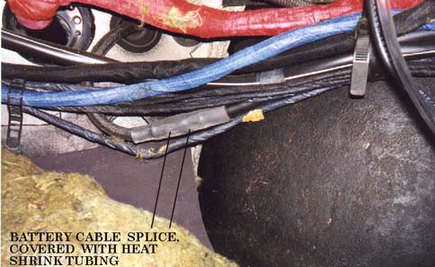
A check under the back seat on my 88 5000TQ shows the positive battery post connection has one large black cable and two smaller ( 6.0 sq..mm) red wires (the two red wires go to the fuse box just as the Bentley wiring diagram indicates). This black cable continues up past where the ECU is mounted under the right front passenger kick panel and is behind the carpet in the right side foot well. The welded connection occurs in this area as shown here with the carpet pulled back for inspection.
One 1988 5000TQ I repaired had a corroded main battery cable at this welded connection and it was too hot to touch when the engine was idling.
The small amount of resistance in this connection was making the battery cable act like a heating element from the charging current that was flowing through the cable from the alternator to the battery! YIKES!
It actually burned the outer insulation tape on the wiring harness that was laying up against this battery cable. The smaller AWG 4 gauge battery cable that exits the passenger compartment and goes to the starter, has a impregnated rubber insulation coating to resist harsh environmental conditions in the engine compartment that is difficult to remove completely for making a new connection. Replacing the entire cable with from this splice to the starter may be necessary if the corrosion has spread to far up the cable. You may also need to replace the entire cable with AWG 2 all the way from the battery to the starter if this cable is corroded heavily all the way up the cable on both sides of the welded connection.
On this one 5000TQ, I only replaced the cable from the splice out to the starter. Disconnect the battery first, then I cut the battery cable near the splice. I bought a 6 foot long battery cable (AWG4 or AWG2 gauge) with the correct lug on it to connect to the starter main connection bolt. There are two cable clamps that need to be removed (Phillips sheet metal screw) that secure the cable/sheath to the frame rail below the air filter housing. If you pop the clips off the air filter housing and move the housing off to the side, you can see both of these screws. The cable is routed through a support hoop near the frame as well. You can reuse the red high temp cable sheath after you remove the old cable.
Inside the car to splice the new cable to the original battery cable, I used a large crimped butt splice connector available at most auto parts stores. I crimped it using some large vice grip pliers and then I soldered it with a small propane torch. I then used several layers of heat shrink tubing to completely cover the new spliced area on the cable. You should remove the cable and pull it out of the car far enough to safely do this soldering.
If you decide to replace the entire cable from the Battery to the starter, you should also remove the passenger seat and the door sill plastic trim to allow pulling up the carpet to gain access to this cable. Use caution when routing the new cable as you don't want anything on the body to rub against the battery cable insulation and cut through to short out this positive cable from the battery.
Cruise Control doesn't work? Foot Pedal Vacuum Switch adjustment ok?
If your cruise control doesn't work, the first thing to check is the adjustment of the vacuum switches mounted on the clutch and brake pedal. Remove the dash lower trim piece to view the location of these switches.
These vacuum switches normally disengage the cruise control if the driver pushes on the clutch or the brake pedal. Often time these switches work themselves out of the retainer and prevent the clutch or brake pedal from fully pushing on the tip of the switch which closes the vacuum vent valve too allow the cruise control system to function. Click or Pop heard in Base Stereo system when A/C compressor is turned on? Intermittent Misfire/Backfire when the A/C is compressor is cycled on? Problem in A/C Control Head Display?
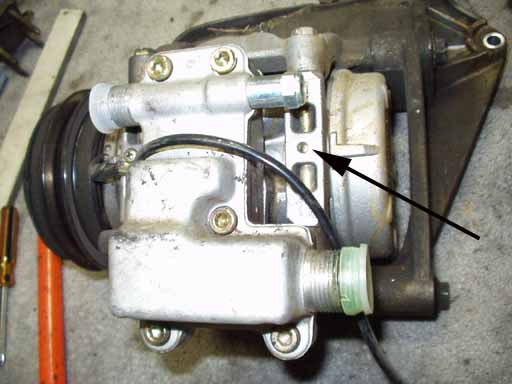
Audi issued a service bulletin, Group 87 # 92-02 on 4/08/92 for the 1988-91 Audi 100/200/V8/80/90 indicating that a new A/C compressor relay and a different compressor magnetic clutch wiring harness with a zener diode was used to eliminate a voltage spike that can occur when the compressor clutch cycles on and off during normal operation.
As of November 1990 Production date, Audi 100/200 after VIN 44MN 024295
and for the Audi V8 after VIN 4CMN001831 the compressor clutch relay
was updated along with a modified A/C compressor magnetic clutch wiring
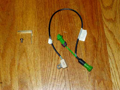
harness with zener diode. You may want to find a suitable zener diode with 18 VDC breakdown voltage soldered or wired to the compressor magnetic clutch +12V wire to ground to suppress these transient voltage spikes. For earlier vehicles produced before the VIN's listed, you can install the new relay and install a zener diode kit for the A/C compressor magnetic clutch wiring.
Updated Harness with clip and screw
The zener diode with bracket, is screwed onto the compressor to provide a ground return path for the diode, there is a bare hole that may accept a self tapping screw as shown here.
Coolant Temp. Gauge, Intermittent Operation? Multi-Function Temp. Sensor
The Multi-function Temperature sensor is mounted underneath the coolant outlet on the cylinder head. It uses a 4 terminal connector which is normally is covered with a protective rubber boot.
The newer style replacement Sensors will have only 3 terminals as they simplified the internal design of this sensor and eliminated the +12V supply to this sensor.
There is a fuse which supplies +12V to this sending unit, fuse #12 should be checked if you have trouble with the temp gauge operation or you suspect a problem with the Multi-Function Temp sending unit.
Go to Cooling System page for more details on this sensor and gauge operation.
Low Speed Radiator Fan and Turbo Cooling Pump After-run Control Unit
The turbo engines have this nice little setup where the turbo cooling pump and the low speed radiator fan come on for a few minutes after the engine is shut down. This allows cooling water to continue to flow through the turbo and the engine to help prevent heat soak after the engine is shut down. Most engines will experience a rapid rise in coolant temperature after the engine is shut down as the excess heat is dumped into the coolant.
Go to the Cooling System page for additional details.
Radiator fan control, 3 Speeds?
The radiator cooling fan is setup to have 3 operating speeds, low speed for when the A/C is turned on and when the after run relay is turned on after shut down. The 2nd speed is used most of the time when the two temperature radiator thermo switch activates at the lower turn on temperature. The 2nd speed fan can also come on from the action of the A/C high pressure switch as the high side pressures increase and the need for more heat transfer over the condenser is required. The 3rd speed or HIGH speed or JET ENGINE ROAR speed is controlled by the two temp radiator thermo switch when the high temp portion of this switch is turned on.
Go to the Cooling System page for more details on trouble-shooting this system.
Radiator Fan FUSE Protection, Retrofit
The radiator cooling fan motor on the 5000TQ and early 89-90 200TQ have a nasty habit of causing a complete meltdown of the wiring harness if the fan motor bearings seize up which creates this huge current draw. The later '90-91 200TQ's added a fusible link which fuses the ground side of the cooling fan motor.
Go to the Cooling System page for details on adding this fuse to your system.
Cruise Control Doesn't work? Rear Diff Locks don't disengage above 15mph? Do you have an aftermarket radio installed????
I ran across a strange problem recently on a 1991 Audi 200TQ 20V. The cruise control didn't work, and the rear differential lock didn't disengage above 15mph as it should. The Bentley wiring diagram shows the speed signal comes out of the instrument cluster and is routed to the cruise control (control unit) and is also routed to the Rear Differential Lock control unit that is located under the rear seat. This signal comes from the instrument cluster from pin T26/2 (Black Connector on right side of the back of the instrument cluster) using a White/Blue stripe wire.
Given all the problems the instrument clusters have on these cars with poor solder joint connections, I made the assumption that there must be a connection problem where the speedo head connects to the circuit board with the two sets of connection pins. Two of the pins are for the +12V and ground, the other two have the signal coming in from the transmission hall effect speed sensor, the other pin is for the output signal that goes out to the cruise control/diff locks.
Well, after taking the instrument cluster out of the car, and repairing the usual suspect solder joints, there still wasn't any signal coming from the speedometer head unit for the cruise control/diff lock. I went so far as to run the car in gear with all 4 wheels off the ground, with the instrument cluster torn apart, while probing the back of the speedometer head unit with an oscilloscope trying to determine why there was no speed signal out to the cruise control/diff lock control units. At one point, I had removed the head unit from the instrument cluster circuit board and had it connected using jumper wires for the +12V, ground and the speed signal input from the transmission. At this point I noticed the speed signal for the cruise control/diff locks was magically there when the head unit was removed from the circuit board which connected it to the wiring that goes out to the cruise control and diff lock control units.
I finally realized that there was something in the circuit that was loading down this speed signal to prevent it from being measured with the oscilloscope. There could be a short in the wiring that goes to the cruise control and diff lock control units or the problem could be in either the cruise control or the diff lock control units. Normally this speed signal used by the cruise control and diff lock control units is a 0-12V square shaped waveform which is low (near ground) about 10% of the time, and high (+12V) 90% of the time. The frequency of this signal naturally depends on the vehicle speed.
I took another look at the Bentley wiring diagram and noticed that there was an additional current track (wire) that was routed somewhere else besides the wiring that went to the cruise control and diff lock control units. This vehicle speed signal is actually sent to the radio! I assume the OEM radio uses this vehicle speed signal to adjust the volume as the vehicle speed increases. Well, come to find out that this car had an aftermarket Radio/CD player installed, and yes you guessed it, they had incorrectly connected this White/Blue stripe wire which carries the vehicle speed signal to the aftermarket radio, which was loading down the signal. Cutting the White/blue stripe wire from the aftermarket radio allowed the correct operation of the cruise control and rear diff locks.
Intermittent Wiper Relay Upgrade- Programmable interval from 2 to 45 seconds Volkswagen dealers sell a replacement Intermittent Wiper Relay that allows you to "program" the intermittent interval from 2-45 seconds. This new relay replaces the standard Audi Intermittent wiper relay which is located in Relay position 9 under the hood on the Audi 5000/100/200 Models. According to the Bosch information on the relay package, this "programmable" Intermittent Wiper Relay fits Audi 100/200's from Aug 1979 and most other Audi models from the late 70's. You adjust the interval by first turning the wiper switch to the intermittent position, and then you turn it off (wiper will wipe once) Now you wait the amount of time you want in-between wiping events, anywhere between 2 and 45 seconds and then turn back on the wiper switch to the intermittent position. The new programmable wiper relay will remember the time you waited in-between turning it off and then back on, and will cycle the wiper once at this new interval. If you want to change the interval again, just turn the wiper off after it wipes once, and then back on after waiting the desired interval. If you turn off the ignition, the wiper relay will default to a 5 second delay when in the intermittent position. NOTE: There is another type of programmable Wiper Relay that
is being sold on most online parts catalogs,
Fog Light Installation 1986-91 100/200T/Q
For those interested in the Fog light (PIAA) installation info, here goes! The mounting is a little tricky, but I will attempt to describe the process. I drilled a 1 inch diameter hole (hole saw) into the plastic spoiler below the bumper face. This allowed access to the plastic bumper bracket that is above/behind the spoiler. I drilled a 3/8 inch hole into the plastic bumper bracket and mounted the fog light to the bracket with a wide washer to distribute the load. In other words the fog light mounting pad goes up through the spoiler and sits flush against the main part of the thick plastic bumper. I located the lights (side to side location) in line with the inner edge of the existing head lamp assembly. Front to back location was just ahead of the long thin grill that is part of the lower bumper/spoiler. You want to avoid blocking the air inlet for the oil cooler and the radiator if you can help it.
The lights protrude out about flush with the front bumper so avoid parking by the feel method. They do look a little weird (People are always asking about them) almost like James Bond rocket launchers but I like seeing where I'm going! So far (one year later) the lights have not been damaged by stones or parking lot mishaps. The lenses are very thick and the housings use powder-coated paint for durability. Some steep driveways do make me a little nervous but so far no problems.
The PIAA 959 lights are 5" wide, 4" high and 5" deep and are oval shaped. It may be worthwhile to find out if PIAA has a thinner (rectangular) light that would not protrude down so far.
I am using the PIAA 959 lights with the crystal ION lenses which produce a yellow light and according to PIAA they do not have the loss associated with regular yellow tinted lenses. I have mine aimed to be just below the bright spots in the low beam headlight pattern. The lights put out a beam of light with a flat cutoff line so aiming is easy.
European Headlamps for the 1986-88 5000TQ, 1989-91 200TQ
Regarding the idea to install High Wattage 9004 Bulbs in the lousy OEM headlights found in the 1986-88 5000T/Q and in the 1989-91 200T/Q. Don't bother.....
Many years ago, before I knew any better, I installed the aftermarket 70/80W 9004 halogen bulbs in my previous 1986 5000CS Turbo which "seemed" to improve the lighting coverage over the standard 45/65W bulbs. At the time, I also installed relays to improve the amount of voltage at the headlight bulb and to avoid toasting the stock headlight switch connections. The headlight switch connections can be toasted while using the stock 9004 bulbs, see information in the next section for more details on this problem. Before I installed the relays, I measured a 1.0 volt drop from the battery to the stock 45/65W Headlamp bulbs. The factory wiring setup runs the full current to the headlamp bulbs through the headlight switch.
Hella published the following values for "Luminous Intensity" which point out how critical it is to get full battery voltage to the headlamp bulbs. 100% voltage is considered 13.5 Volts for the 12V system. Using relays can help even the marginal stock headlamp performance by providing full battery voltage to the light bulbs.
The High Wattage 9004 bulbs were more trouble than they were worth, they only lasted 4-6 months and they would burn up the stock 9004 connectors unless you beefed up the wiring or purchased the high wattage 9004 connectors. Finally, one day after using the high wattage bulbs for about a year, and yet another High Wattage 9004 bulb burned out, I replaced it with the stock 45/65W 9004 bulb I had for a spare. I couldn't really see much difference in the light output with one stock bulb in one side and one High Wattage bulb in the other side. The OEM Headlamp optics are so poor and when you combine this with a pitted headlamp lens from old age, you end up with very little light from these units even with high wattage bulbs. I ended up going back to using the stock 45/65W bulbs on this car. I now believe that the main change in headlamp brightness occurred from adding the relays to the system and very little benefit came from the high wattage bulbs.
Now that I have installed the European Headlamp system on my 1989 200TQ, I can confidently say: Don't waste any time or any money screwing around with high wattage bulbs in the stock headlamp system on these cars. If you run the stock headlamps, you SHOULD install relays as mentioned above, but I don't think the high wattage bulbs are worth the aggravation. Save your money and if you decide to keep your car for several years, just bite the bullet and purchase the European headlamp system. You can install the larger Audi 100 style european headlamps if you change out the front grill, these european headlamps were sold in the USA by many Audi dealers, and can be found in some wrecking yards. They were made by both Hella and by Bosch. Lately there are some Asian made knock offs available for these Audi 100 style european headlamps, ImportVIsion.com is one company that sells them. The quality isn't great but they do have glass lenses and accept the single H4 bulb. They have no center driving light as was used in the Audi 200 headlamp, but work much better than the lousy 1986> Audi 100 or Audi 200 US DOT approved Headlights. The Audi 200 style Euro light system is expensive at $700-800 and are getting much harder to find, and may be obsolete. Both the Audi 100 and Audi 200 have much better glass optics with a flat cutoff. The Audi 200 european lights use the H4 low/High beam bulb and the Center H3 driving light bulb. Even with the whimpy 55/65 Watt H4 and the 55 Watt H3, these Euro lights are incredible! They produce a nice flat cutoff in the low beam and a great high beam pattern. I can't imagine what these Euro lights would be like with a 80/100 Watt H4 bulb, and the 100 H3 bulb that many people use, eventually I will test this setup out, but for the now the 55/65W H4 and 55W H3 lights are wonderful.
On my previous 5000T, I did install some PIAA 959 projector fog lights which do a great job of illuminating the front and sides of the road during heavy rain, snow or fog. They are 85 watts each and produce a flat beam of light because of the projector design. Before purchasing the Euro Light system, I transferred these PIAA 959 to my 1989 200TQ and they "may" be useful in heavy fog or heavy snow fall even with the Euro Headlight system.
European Headlamp Installation, 1986-91 5000TQ/200TQ
Click here to go to the new page for the European Light Installation information.
Low Beams Inoperative, Headlight Switch Connector 1986-91 5000/100/200TQ
If the low beam headlamps suddenly stop working and the fuses and bulbs check out ok, you may want to pull the top plastic cover off of the steering column combo headlight/wiper/turn signal/emergency flasher switch to inspect the connectors. Pull off the connector for the headlight portion of the combo switch and check the connector for a burned terminal. My 89 200TQ lost the low beams intermittently and I found that Audi used a small terminal to carry the low beam current through the headlight switch. Mine was toasted!
The high beams use a larger terminal. I was able to replace the plastic portion of the connector and I soldered in a new terminal that I bought from the dealer. Luckily I was able to clean up the headlight switch terminal and did not have to replace the switch assembly.
I would recommend installing relays near the headlamps even if you are running the stock bulbs. Audi chose not to use any relays for either the low or high beams. I did not want to risk burning up another connector or switch.
Power Window Switches and Side Mirrors inoperative?
The wiring that is run through the drivers door for the electric window and side mirrors often gets stressed to the point where several wires break inside the taped up loom. You can sometimes crimp/solder these broken connections and use heat shrink tubing to seal it all up. It may also help to loosen the loom connection under the dash to allow pulling the loom out for easier repair and allow it to flex in another position.
Power Window Switch Cleaning
All this discussion on window problems has motivated me to pull out the drivers side window switches (86 5000CST) and give them another cleaning.
The main panel holding all the switches pulls up and out with a gentle prying action from a screwdriver. Unplug the four connectors for the windows, the two for the mirrors, and the one for the rear window lockout switch. Remove the metal retaining clip on the main panel. The window switches pop out of the main panel by prying from the center towards the side. There are four tangs holding the switch into the main panel. Now the switch can be disassembled by prying the four tangs and sliding the plastic cover off. It is a little tricky getting all four of the tangs to release at the same time. The switch contacts and the Light Emitting Diode (LED) with resistor can be seen. Use emery cloth or sandpaper to remove any pitting or crud from the contacts. Contact cleaner can be used to flush out any residue. I replace one of the dead LED's while I was in there.
Power Window Regulator Problems
Many years ago, my drivers side power window regulator made this crunching sound (86 5000CS T) just before it quit. I took the door panel off and found the cable that pulls the window up and down had come off the lower plastic pulley. The reason it came off was that the plastic guide tube on the motor assembly had broken and the cable tension went to zero and the cable got tangled up in the motor pulley. I was able to repair it back together over the weekend by clamping part of a copper pipe around the broken plastic section. At the time, when these regulators were not available in the aftermarket, I checked out the new part from the dealer and it looks like Audi added a clamp around the section that typically breaks off. Other problems include issues with the motor commutator brushes getting worn out, or sticking, in some cases water gets inside and causes corrosion damage. The motors can be swapped between a good and bad window regulator, but requires removing the cover over the cable spool, carefully removing the cables with spool gear, drive isolators, and main drive gear so the motor shaft with gear teeth can be removed after removing the 2 philips screws holding the motor to the regulator. Fast forward several years....fortunately, now some of the Aftermarket parts suppliers have the OEM type cable operated window regulators available.
1992-95 Audi 100/S4, Window Relay Rapidly clicking On/Off? Battery going Dead? Windows and Sunroof closing by themselves?
Back in 1999, I ran across a weird problem on a friend/customers 1992 Audi S4. He told me that at random times he would come back to his Audi to find that all the windows and sunroof had closed on their own. Huh? The other random occurrence was he would hear a loud clicking sound coming from the bank of relays in the drivers side kick panel under the dashboard. The battery would be quickly drained from this fun little exercise and the relays behind the kick panel would get very hot. Trying to predict "when" this relay clicking problem would occur was not very straightforward. Here is what I found out by spending a day trouble-shooting this car...... :-( The Central locking/Alarm system/Interior light Delay Control Module (V94) which is all incorporated into the door lock Vacuum pump assembly under the back seat, next to the battery, controls this feature which allows closing all the windows and sunroof from the front door lock/key switch.
Here is how the system works: When the driver is locking the car door, and holds the key over to close the windows and sunroof, a signal from the door switch is sent to the Central Locking/Alarm module V94. On the V94 there is a yellow wire at pin #8 (Designated T16/8 in the wiring diagram) which then provides a ground signal to the Power Window Control Module (J139) on pin 10/SK. Then the J139 Window Control Module sends a signal to the Automatic Window Closing Relay (J261) (short stubby 50A relay) to initiate closing all the windows and sunroof. The (J262) relay is activated by pin 6/KR from the (J139) window control module. The (J139) control module and the (J261) relay are located behind the lower left kick panel cover, drivers side. If the car battery voltage drops down below normal, the voltage on this yellow wire T16/8 will also drop down towards 9-10 volts, and at some voltage near 10 volts, the Power Window Control Module (J139) will begin to oscillate and rapidly turn the Window Closing relay (J261) on and off in a most bizarre fashion. I was able to duplicate this random problem repeatedly by using some 5-10K ohm resistors to load down the voltage on this yellow wire T16/8 until the problem would begin to occur. On my friends 1992 Audi S4, the aftermarket radio had been installed incorrectly, and was draining the battery down slowly over time. Keeping the battery charged at the normal voltage "seemed" to prevent this problem from occurring. Disconnecting this T16/8 yellow wire from between the (V94) Central lock/Alarm unit and the Window Closing Unit (J139) will also prevent this problem from occurring, and you only lose the window/sunroof closing feature using the door key. The windows and sunroof work normally from inside the car. I suspect there is a problem with the drive circuitry inside the (V94) central locking/Alarm control module. The logic circuit inside the (J139) Window Control Module could also use some redesign to prevent this odd behavior when the drive voltage is somewhere near 9-10 volts. This J139 relay is expecting the control voltage to either be close to ground potential 0.0-2.0 volts when the automatic window/sunroof closing is activated, or up near +12-14V. My friend did not want to fork out the cash to buy a new V94 Central Locking/Alarm etc. unit to see if this would completely eliminate the problem, so I cut the Yellow wire at pin #8 on the V94 Central Locking/Alarm module (Designated T16/8 in the wiring diagram) and disabled this automatic window/sunroof closing feature.
At the same time my customer was having this problem , he had talked to another 1993 Audi 100 owner, who had his car at the Audi dealer with this same problem, the dealer had replaced the (J139) module and the (J261) relay but this did not solve the problem.
Some time later I found out that the V94 Central Locking/Alarm module had been superseded to a 4A0 862 257J, instead of the earlier 4A0 862 257B, D versions. So, it looks like the complete solution is to replace the V94 Central Locking/Alarm/Interior Light module.
The Window/Sunroof Relay has not been superseded, and the Audi dealer is still showing the 441 959 257B as the correct part. I suppose it is possible for the J139 Window Control Module or the J261 Window closing relay to be damaged if the rapidly clicking on/off problem happens for too long as these relays can get very hot.
During the last few years, I have talked to several other Audi 100/S4 owners who have also experienced this weird window relay clicking problem when their battery was partially discharged.
Rear Window Defroster Inoperative
The Rear Defroster switch can have intermittent operation due to some lousy contacts inside the dash mounted switch. This can occur even if the rear defroster switch light comes on when you push the switch. I attempted to clean the internal contacts on the switch, but eventually bought a new one as the old one was still intermittent.
In some cases the actual heating element traces on the rear window can get damaged. Some auto parts stores carry some trace repair fluid for repair these breaks. The Wagons can have problems with the wiring that is run through the rear hatch at times as well.
Starter No Click? No Cranking? Audi 100/200 Alarm System problems
The 1989-91 Audi 100/200 came with a factory installed alarm system which has a starter solenoid circuit interrupt if the car has been broken into after being locked. The system uses an Anti-Theft relay to interrupt the starter solenoid signal from the ignition key.
If your starter doesn't click when you turn the key, meaning the starter solenoid isn't engaging when you turn the key to start position, you may want to remove the Anti-Theft Relay in Position #8 under the hood in the main fuse box and jumper across the large terminals #36 and #38. This jumper will ensure the Starter solenoid is getting the start signal from the ignition switch.
In some cases the alarm system has gone haywire or the door lock switches are broken and the system thinks you are trying to steal your own car.
A defective ignition switch can also cause a no start condition. Also check the solenoid wire and connection at the starter, in some cases, this wire gets corroded and can short to the engine block or starter housing.
Smoke coming from out of the turn signal, headlight, or wiper switch on 1989-91 Audi 100/200?
If you notice some smoke coming out of the combination column switch assembly, you may have suffered a mild meltdown of the switch contacts or you have some grease/copper burning inside the switch.
The combination switch is made of a left and right side pieces, the smoke can come from either side section of the switch. The left side contains the turn signal, or headlight switch, the right side portion of the switch has the wiper, hazard switch, and the trip computer button.
Grease is used to lubricate the copper contacts inside the switch,
and often times the grease contains the copper contact particles that
are sloughed off during wearing of the contacts and this grease/copper
mixture eventually conducts electrical current and can burn up creating
the smoke. In other cases the contacts have worn enough to create so
much resistance that the contacts melt from the current flow.
Ticking Noise under 200TQ Dashboard
I had a chattering/ticking sound coming from one of my relays under the left side of the dash recently, this only happened when the engine was warm/hot and the outside temp was 80+ F. I found out that the injector cooling fan sensor which is mounted on the exhaust heat shield had a loose connection terminal. This loose connection was turning the relay on and off rapidly which made the relay sound like machine gun fire. If your ticking noise is happening when the engine is cold you may want to check the idle stabilizer relay. It is the double wide relay behind the drivers side knee panel. If memory serves me, last year I needed to take mine apart and fix a poor solder joint. I assume the ticking that you are hearing is not coming from the seat heater relays, a clicking hydraulic lifter or from an exhaust leak. (1/98)
W = White BK = Black OR = Orange BR = Brown CL = Clear R = Red Y = Yellow G = Green BL = Blue V = Violet (purple) GY = Gray LT.G = Light Green
Note: Two color description means the wire has a main color and a "tracer" stripe along the wire of another color.
i.e. R/Y = Red wire with Yellow Stripe
Wiring Size, Metric Conversion to AWG
Copyright © SJM Autotechnik™ , all rights reserved
Return to Troubleshooting Tips page. Return to SJM Autotechnik™ main page.
|
||||
| About Us Privacy Policy Terms of Use Links Customer Service Safety Information Home |