|
European Headlamp Installation, 1986-88 5000 Turbo/Quattro, 1989-91 200 Turbo/Quattro
SJM Autotechnik™ : European Headlamp Installation, 1986-91 5000TQ/200TQ
Remove the front grill, there is one screw on top and three screws on the bottom behind the rubber strip. You need to pop loose the thin pieces of trim that snap into the right and left headlamp assembly. The grill is then pulled forward and then up. Remove the one screw towards the inner end of the headlamp assembly. Remove the one screw on the bottom of the right and left headlamp assembly that secures the center chrome strip and remove this strip. The side chrome strip Phillip screws need to be loosened to allow them to be pulled slightly outward to get to the lower/outer screw that secures the headlamp assembly. You can remove the front bumper to get to these screws if you want or you can sneak a screwdriver in between the bumper plastic and the strip to loosen these screws. There are two 8mm screws on the top sheet metal that hold the headlamp assembly.
Before you install the new headlamp assemblies, there is one screw hole missing on the Euro Lights for the side/front Chrome strip. There is a plastic boss on the Euro Light assembly where you can drill a hole to use a self tapping sheet metal type screw to duplicate the original mounting. It helps to drill this hole before you install the Euro Lights. Installation of the new Euro Lights is fairly straightforward, you have to wiggle them in and watch the upper rubber seal. You may need to relocate the wiring harness behind the lights a bit to get the new assembly in place.
Bulb Wattage selection
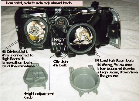
The Euro Lights use the H4 dual filament bulb, the stock Low beam wattage is 55W, High Beam is 60W. The Euro lights also have a center driving light which use a 55W H3 bulb, this H3 driving light is normally wired to the High Beam H4 bulb inside the housing so that both the H4 high beam and the H3 driving light come on at the same time. There is a 4 Watt "city light" bulb below the H4 bulb inside the main headlamp assembly. This city light should be connected to the existing parking light wiring. Some people upgrade the H4 bulb to a higher wattage 100/55W or higher 100/80 watt and also use a 100 watt H3 bulb, but I have not tested out these higher wattage bulbs.
If you have the Euro lights for the non Turbo Audi 5000 or Audi 100, the H4 bulb is wired as follows:
Looking at the back of the H4 bulb, here is the pin connections:
___ (Yellow wire-Low Beam)
| (Brown wire-Ground)| (White wire-High Beam)
Here is a photo showing the location of the 3 bulbs (H4, H3, and city lamp). Also shown are the Horizontal (side to side) adjustment and the Height (Vertical) adjustment knobs as well as the vertical adjustment lever. It takes many turns on the horizontal adjustment knob to make much difference in the horizontal position.
The gray colored vertical "Height Lever" should be in the down position during normal vehicle use and during the headlamp adjustment. These levers can be pulled to the up position if the trunk is heavily loaded to avoid blinding on coming traffic.
Electric Motor Adjusters
Some people have also fitted the European electric motor Headlamp adjustment system on their vehicles and this system allows height adjustment of the Euro headlights from inside the vehicle using a thumb knob. The adjustment motor replaces the height adjustment knob/lever assembly. The part number for the Euro headlight motor is 443-941-295 (2 required), the thumb knob switch is 447-941-301A, 01C? These adjustment motors and switch may be only available from Germany. There are also some manual pull rod shown in the Euro parts fiche for manual operation of the up/down gray lever. 447 941 299C (left) and 447 941 299D (Right)
Wiring Connections
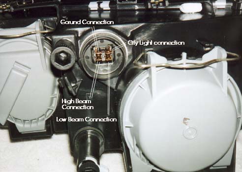
Here is a photo showing the wiring of the 4 pin connector at the back of the headlamp unit.
Looking at the back of the headlamp assembly connector
NOTE: A few folks have received European headlamp units which apparently did not have the same (symmetrical) wiring pin out for each side. You may want to take a look inside each headlamp unit and trace the wiring from the terminal pins to the bulbs, to ensure that each side is wired the same, before completing the wiring on the connector for each side. In some cases, the connector is rotated 180 degrees from what is shown above.
Installation Details
On the 89-91 200TQ you may need to relocate the battery jumper post to the side/rear a little to clear the Larger Euro headlamp assembly. Most people who live in mild climates will install relays near the headlamp assembly when installing Euro Lights and connect the relays to the battery jumper post for the main +12V supply.
Using a good aircraft or commercial style ratcheting type crimping tool is also important to avoid problems with your wiring connections.
The Eurolight connector terminals are Audi Part N 017 491 8 require the use of a "non insulated" terminal crimping tool that folds over the metal terminal at the wire and over the insulation.
I use the Ideal brand "Crimpmaster" ratcheting crimping tool with #30-586 crimping die for the non insulated terminal crimping.
The Ideal #30-579 die can be used on the regular "insulated" terminals.
The Eurolight plastic connector blocks that accept these crimp terminals are Audi part # 447 972 957, your local Audi dealer may be able to order these. The rubber boots Audi part # 447 941 189 have been obsoleted by Audi. There may be another rubber boot available from Audi that could be substituted for this boot but we have nothing available. The Bosch relay 0 332 209 150 has a mounting tab and can be used to make up your own wiring harness with relays.
If you live near the ocean or in an area where they salt the roads in the winter, you may want to locate the relays somewhere inside the passenger compartment or use a sealed relay enclosure to avoid corrosion of the relays and terminals. If you mount the relays inside the car, you would have to run the heavy gauge (10 or 12 AWG) wire from the battery to the relays with some inline fuses, and then use 12 gauge wire from the relays out to the Euro Headlamp connector. It may be possible to mount some additional relays in the main fuse/relay box under the hood but I have not tried doing this yet.
Mounting the relays inside the vehicle, involves more work, and requires attention to detail if you are routing the heavy wire through the firewall. Make sure that any wires you install have rubber grommets to avoid chaffing against any body metal or any other hard trim pieces that may cut through the wire over time from vibration. Use available plastic harness covering to protect the wiring in these areas.
THE COMMON 12V AUTOMOTIVE BATTERY WILL PROVIDE ENOUGH CURRENT (HUNDREDS OF AMPS) TO CAUSE A SEVERE ELECTRICAL FIRE IF ANY UN-FUSED +12V (Positive Battery Connection) WIRE IS SHORTED TO THE VEHICLES BODY (Negative Battery Terminal)
IF YOU ARE UNFAMILIAR WITH MODIFYING THE ELECTRICAL WIRING ON YOUR VEHICLE, YOU SHOULD CONSULT A REPUTABLE REPAIR SHOP FOR ASSISTANCE WITH THIS TYPE OF WORK.
Whenever you connect a wire to the Battery +12V supply directly or from the battery jumper post, you should use inline fuses close to this connection in the event the wire shorts to ground somewhere between the battery and the relay or between the relay and the headlamps.
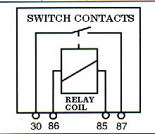
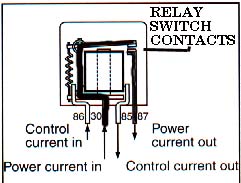
Here is a diagram showing the typical relay connections and a diagram showing how these connections operate the relay and supply current to the headlamps.
Diagrams courtesy of Hella corporation You can use one relay to operate both High Beams, and another Relay to operate Both Low beams, this involves running the wire from each relay over to both side lights. Some people use two Relays per side, for a total of 4 relays, one for each high beam and low beam bulbs on each side.
Using the diagram, Terminal 30 (+12 Volt Source) is normally connected to the battery post via a fuse, Terminal 87 (Relay output to the load) connects to the headlamp bulbs (High or Low beam) . Terminal 86 (Relay coil control signal) connects to the original headlamp wiring Yellow or Yellow/Black (low beam) and the second Relay terminal 86 would connect to the White or White/Black (high beam) wiring. Terminal 85 (Relay coil ground) is typically grounded , you can use the original headlamp brown ground wire for this or ground to the vehicle chassis/body nearby the relay. Again, if you live in an area where they salt the roads, make sure to protect the ground connection on the frame with appropriate primer/paint or other type sealant (undercoating etc. )
If you install the relay next to the headlamp assembly, try and locate the relay out of the way so that you can replace the H4 and H3 bulbs without having to remove the headlamp assembly. Make sure you don't block the air intake for the 1986-90 10V Turbo engine and especially on the 1991 200TQ 20V engine. Make sure the Inline fuses and relays are mounted or hung, so that water will drain down and out and not collect inside the fuse or relay. Using a water tight enclosure to locate the relay inside is also a good idea to avoid corrosion problems. When installing the Euro Headlamp assemblies, I usually cut off the stock 9004 headlamp connector and use some good butt splice connectors to connect to the existing wiring. Heat shrink tubing that has the sealing goo inside, can be used to protect these butt splice connections. You could also solder the wires together and use some heat shrink tubing to seal the connection.
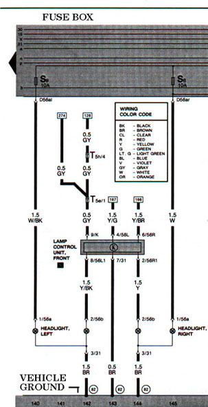
The existing low and high beam wiring (yellow and white wires) should be connected to control the relays. Here is the original wiring diagram for the stock DOT headlamps on the 1989 200TQ.
Diagram courtesy of Audi America
The rubber boot that covers the Euro Headlamp connector will help to keep moisture out and avoid any corrosion at this important connection but these have been obsoleted by Audi. There may be other boots you can substitute.
The clamp on scotch type connectors that cut into the wire don't work that great when exposed to moisture and I don't recommend using them.
The existing ground wire in the headlamp harness, can be used to supply a ground to the new relays.
I also recommend connecting a heavy gauge local Ground wire down on the frame or connected to the engine block instead of using the existing headlamp harness ground wiring that consists of a small diameter brown wire.
Once gain, if you live near the ocean or in an area where they salt the roads, make sure to protect the ground connection on the frame with appropriate primer/paint or other type of sealant (undercoating etc. ).
I used one DUAL relay on each side for the High Beams and the Low Beams. In other words, the low beam and high beam wiring on each side has its own relay for a total of 4 relays . As mentioned, you can also use one relay to supply current for both side low beams and one relay for both side high beams to get by with two relays. 12 gauge wiring is plenty big to handle the current.
A rough calculation for the current flow through the bulbs is to divide the bulb wattage by the charging system voltage to get the current. 65Watts divided by 13.5 V equals 4.8 Amps. 100Watt bulbs use 7.4 Amps. Some people install higher wattage bulbs, for instance 80/100W H4 and 100Watt H3 bulbs, in this case with the high beams on you have 200Watts/13.5 volts = 14.8 amps per side!
Auto-Check System modifications:
There are a few ways to disable the Auto-Check system to avoid getting the warning when you install the relays for the front headlamps. The "Lamp Control Unit - Front" will need to be removed temporarily and the Terminal "9" connector wire (Gray wire) disconnected from behind the unit connector. This gray wire connects to the "K" terminal on the "Lamp Control Unit". Instead of disconnecting the gray wire from the "Lamp Control Unit, the "K" terminal can be bent over out of the way, or I suppose you could just cut off this "K" terminal completely. After you finish modifying the wiring or the "K" terminal, make sure to re-install the "Lamp Control Unit" to eliminate the Headlamp Warning signal.
You can also remove the Lamp Control Unit completely and make up some jumper wires with the appropriate male connectors to replace this control unit altogether and effectively jumper between 56L1 and 56L and between 56R and 56R1 terminals respectively on the Lamp Control Unit. This corresponds to connecting between terminals 4 and 8 and 6 and 2 respectively on the relay panel connector where the Lamp Control Unit plugged into.
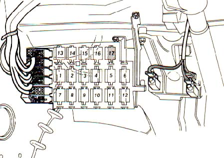
This Lamp Control Unit resembles a relay and is located in the #5 position in the auxiliary relay panel under the drivers side dash. The #5 position is on the center row, the 5th relay on the right as shown here.
Diagram courtesy of Audi America
On the 1989-91 200TQ with the airbag, to gain access to this Lamp Control Unit, you need to remove the large panel under the dash which functions as the knee bar. The side trim panel has to be removed first to get at the two screws for this lower dash panel (knee bar). There is one screw underneath at the bottom left, that retains this side panel, and then the side panel must be pulled down slightly and then wrestled up once the upper retaining tangs are down and out. There are two screws behind this side panel that retain the lower dash panel (knee bar). In addition there is one screw under the steering column area and one screw at the bottom lip of this lower dash panel that must be removed to get this lower dash panel (knee bar) pulled out. Getting the side panel back in place after re-installing the lower dash panel is a bit of a pain.
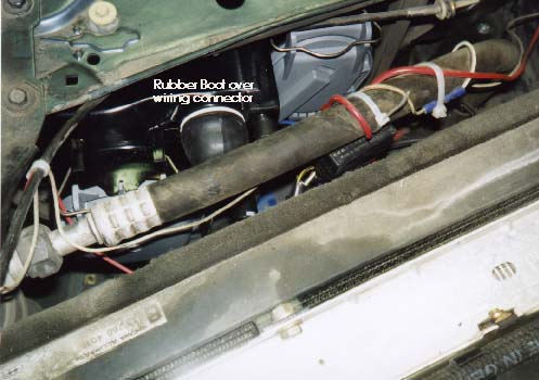
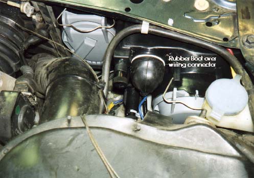
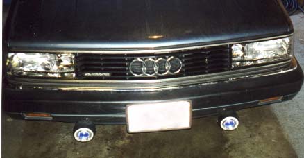
Here are two photos showing the area behind the left and right headlamp after installation of the Euro lights.
Here is what the front of the car looks like with the Euro Lights installed. Those funky looking lights under the bumper are the PIAA 959 Fog lights, I have not yet decided if I am going to yank them off.
SJM Autotechnik™ : Wiring Color Code Chart
W = White BK = Black OR = Orange BR = Brown CL = Clear R = Red Y = Yellow G = Green BL = Blue V = Violet (purple) GY = Gray LT.G = Light Green
Note: Two color description means the wire has a main color and a "tracer" stripe along the wire of another color.
i.e. R/Y = Red wire with Yellow Stripe
SJM Autotechnik™ : Wiring Size, Metric Conversion to AWG
Copyright © SJM Autotechnik™ , all rights reserved Return to Electrical Troubleshooting Tips page. Return to SJM Autotechnik™ main page.
|
||
| About Us Privacy Policy Terms of Use Links Customer Service Safety Information Home |