
|
ur-Quattro,Technical Tips Engine Cutout problem, ECU Tests, Fuse Box Problems
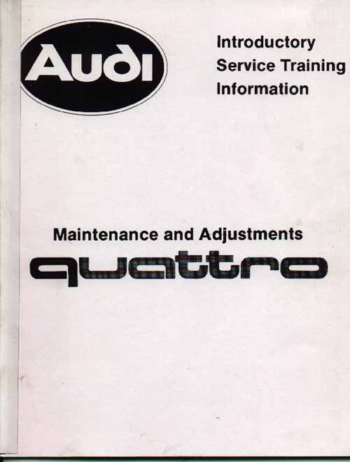
Ur-quattro factory Preliminary repair manual and Introductory Service Training (IST) booklets.
There are two "Highly Recommended" Audi Factory Introductory Service Training books that outline the diagnostic procedures described below, as well as covering many other important systems in the ur-Quattro. These may be available online, search the Internet to locate them.
The ur-quattro uses a Hitachi MAC-02 designated Engine Control Unit that takes in information from several components designed to monitor engine operation. Engine Speed, Crankshaft position, Camshaft position via the Distributor position, Intake Manifold Pressure, Intake manifold air temperature, Coolant temperature and throttle position at idle and full throttle switches provide this information to the ECU [8].
The ECU then adjusts engine timing and fuel requirements for all engine operating conditions.
The CIS frequency valve is used to adjust the amount of fuel the engine receives by changing the pressure drop across the slit in the fuel distributor plunger which delivers fuel out to the injectors. Higher duty cycle percentages means more fuel to the engine and slightly richer mixtures.
The ECU does this by varying the duty cycle percentage of the Pulse Width Modulated (PWM) electrical signal that drives this frequency valve. The duty cycle referred to in this discussion is the "negative" duty cycle, or the percentage of time the signal sent to the frequency valve is low near ground potential. Some Digital Multi-Meters (DMM) can show you the positive and the negative duty cycle, be sure you have the meter set up correctly to read the negative duty cycle. The other thing to pay attention to is how you connect your meter to the brown and blue wires at the test connector.
A dwell meter normally is setup to only read the negative duty cycle of signal. When using a dwell meter set to the 4 cylinder scale, a Dwell of 45 degrees, equals a 50% duty cycle, i.e. 50% of 90 degrees, or 0.50 times 90 degrees equals 45 degrees.
The frequency valve normally receives a constant +12 to +13.5V volt on one wire and the ECU grounds the connection to the valve to turn it on for a percentage of time. A 40% negative duty cycle means the signal driving the frequency valve turns on the valve 40% of the time, then off for the remaining 60% of the time. The PWM signal that drives the frequency valve has a frequency of ~70Hz, but it is the duty cycle of this signal that is important.
A graphical picture of this signal can be found on this page......
Link to Oscilloscope waveforms
The coolant temp sensor provides the ECU with cold starting and initial cold running information. During the engine warm up phase, when the ECU controlled fuel system is in open loop mode, without the Oxygen sensor signal being used, and the engine coolant temp below 32C (90F), the frequency valve duty cycle should be set somewhere between 65% and 42%.
It will be at 65% when the engine coolant temp is at -10C (14F) or colder. It will drop down below 50% as the engine coolant temp passes through 20C (68F), then it will go down further to ~42% as the temp passes through 25C (77F), and start to go back up to 50% duty cycle after the temp gets up to 30C (86F) and above. This drop down to 42% can often cause the engine to run too lean during the warm up phase, and cause a momentary gag in performance until the engine temp gets above the 30C (86F) mark.
This is especially true for ur-quattros that no longer are using the stock camshaft. These cars have lousy idle engine vacuum due to the longer duration camshaft, and this can cause poor cold running and a rough warm idle. A richer open loop basic idle mixture setting may be required to get these cars to run ok when cold.
I suspect the drop down to 42% was done to reduce the emissions of the engine during the warm up phase to meet the strict Federal emissions requirements back in 1983.
The normal Carbon Monoxide (CO%) reading upstream of the catalytic converter for the stock ur-q engine, should be set between 0.6 to 1.2% when the engine is warmed up, and the O2 sensor is disconnected, along with the breather hose disconnected and plugged where it connects at the valve cover, and with the fuel vapor line disconnected from the intake boot aluminum housing. Setting this CO% to the high end of the range, (1.2%) will provide better initial cold running due to the richer mixture. An even richer setting may be required on the vehicles with modified non-stock camshafts.
This 0.6% to 1.2% CO%, corresponds to a frequency valve duty cycle when in closed loop, with the oxygen sensor connected, of somewhere between 42-58%.
The coolant temp sensor will also influence the cold starting cranking duty cycle enrichment value, if the coolant temp is below 60C, (140F) the duty cycle during cranking will be at 80%, if the coolant temp is above 60C, (140F) the ECU will set the cranking duty cycle to be at 50%.
ur-quattro Engine Control Unit (ECU) Diagnostics
The following diagnostic tests can be done to verify correct ECU and system operation.
With the engine warmed up, and idling, you can run some diagnostic procedures to verify the Oxygen Sensor Mixture Control system is working correctly. Connect a Duty Cycle Meter or Dwell meter (4cyl scale) to the two pin connector (Blue and Brown wires) behind the intake manifold area. Do not connect directly to the frequency valve connection.
NOTE: 4 cylinder Dwell of 45 degrees, equals 50% duty cycle, i.e. 50% of 90 degrees, or 0.50 times 90 degrees equals 45 degrees
TEST 1: Manually push the full throttle switch closed and note the Duty cycle, it should have a steady reading of ~50%.
TEST 2: To check full throttle enrichment, with the engine running at idle, remove one wire from the idle switch and then push the full throttle switch closed again. You should see a duty cycle reading around 70-77%.
TEST 3: Check cold start cranking enrichment: Disconnect the oxygen sensor, and then disconnect the coolant temp sensor wire below cylinder #1, Ground the coil wire, then crank the engine while viewing the Duty cycle. It should read ~80% during this test.
TEST 4: Check Cold running enrichment: Start the engine, then disconnect Oxygen sensor wire, and then disconnect the coolant temperature sensor, the frequency valve Duty cycle should go to ~95% for up to 30 seconds, and then duty cycle should be set to ~65%.
Air Temp Sensor Connections? 4000 RPM Fuel Pump Cutout (Cycling on/off)
I have run into several 83 ur-Q's that had problems that were causing the engine to cut out at 4000 RPM and at random times. Here is some info that may help.
These cars had several problems that were making the car cut out, sometimes a fuel pump cutout, sometimes an ignition system cutout, sometimes while cruising along, sometimes while under heavy acceleration/high boost. Sometimes, sometimes, sometimes..... The darn cutout problem(s) were very intermittent and it was very tough to get these to fail WHILE you were driving it.
I have used several kinds of DMM's, oscilloscopes etc connected up to these cars to monitor ECU, Ignition coil, Ignition Control Unit signals while I was driving along to help find some of the problems listed below.
AIR TEMP SENSOR CONNECTIONS
The first problem I usually find is that the air temp sensor wires were frayed which caused an intermittent connection at the sensor. The ECU will shut off the fuel pump when the RPM goes above 4000 RPM if the Air temp sensor is defective, in a sort of limp home mode. The ECU cycles the fuel pump on and off, every second or so when this limp home mode occurs. If the idle switch gets shorted out when the throttle is opened, the car will also go into this limp home mode.
Rumor has it that a defective coolant temp sensor or wiring will also cause this limp home mode, but I have yet to confirm this. Probably a good idea to check the coolant temp sensor connections and measure its resistance while you are at it.
Because the air temp sensor resistance is very low (13-33 ohms at room temp) to begin with, the ECU can freak out if there is a poor connection at the ECU connector or out at the air temp sensor itself. Replacement push on terminals are available that fit over the small air temp sensor terminals. The original air temp sensor wire connections may have been spot welded or soldered on as was done with the later 5000TQ air temp sensor. The air temp sensor connects to the ECU at Pins 18 and 19, and you should normally see around 70-140mV (0.07V to 0.140V) across these terminals. Some ur-Q owners have gone as far as hard wiring the air temp sensor connections inside the ECU to avoid any connection problems at the ECU.
SHORTED IDLE SWITCH or WIRING?
Some of these vehicles were still getting an occasional fuel pump cutout at ~4000 RPM and the problem was traced to the idle switch assembly. If the internal idle contacts or wiring are shorted together when the throttle is open this can also cause the fuel pump cutout at 4000 RPM and the timing can be off.
If the idle switch is open circuit or the wires from the switch to the ECU are broken, there will be no cold engine idle timing advance when coolant temp is below -3C.
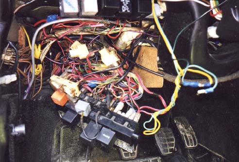
The second most common problem was with the fuse box round pin terminals at the back of the fuse box. As can be seen in this picture, the ur-Q fuse box wiring leaves a bit to be desired.
As the Apollo 13 captain said "Houston we have a problem!"
The Terminal 15 connection (Main Ignition switch +12V) at the back of the fuse box is done through a small diameter pin connector designated on the wiring diagram as E2. (1983 Ur-Q) .This one pin connector supplies +12V to the ECU and fuel pump relay, the Ignition coil, the turn signal, the dash gauge assembly, the seat belt warning light etc. This one pin has a bad habit of getting hot and then it gets toasted due to the high amount of current flowing through this small connection.
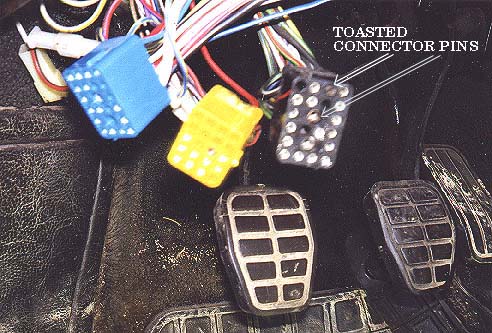
Here is a photo of one of the fuse block connectors with burned up terminals.
The connections that leave the fuse box and go to the Ignition Coil (C15) and the ECU (A11) can also get toasted. This was the case with this problem 1983 Ur-Q, the car would cut out while driving, especially if the turn signals were on. The seat belt light would begin to glow and then the tachometer needle would swing up and down or in some cases it would drop dead altogether and finally the car would die from the loss of ignition +12V supply.
If you suspect the fuse box is causing the problem, you should pull it partially out and remove the back connectors, one by one and look for toasted terminal pins. I ended up rewiring the +12V supply to the ECU and the Ignition Coil and removed these connections from the fuse box and wired them directly to the main +12V (Terminal 15) feed from the ignition switch. The +12V supply to the ECU and the Ignition coil was not fused previously anyway.
I usually leave E2 connected to the fuse box to allow the turn signals and instrument panel stuff to still get the ignition power, you want to make sure this E2 pin is not burned up, replace the pin/connector pin in the plastic connector block if necessary. I modify the wiring by cutting this E2 wire between the ignition switch and the fuse box connection several inches before it enters the back of the fuse box, and then splice into the cut connections and connect the wire from C15 for the ignition coil (cut C15 wire from back of fuse box) , and also cut and splice in the A11 wire from the back of the fuse box connector plug, as this wire provides power to the ECU and the fuel pump relay.
Effectively you are cutting the (terminal 15) black wire that goes from the ignition switch into E2 and then reconnecting this wire but are splicing in the wires from C15 and from A11 "before" the fuse box connection at E2. This way C15, and A11 do not rely on getting power through the fuse box and always get ignition power directly from the ignition switch. The original E2 pin connection at the fuse box ends up only supplying power to the turn signals, instrument panel stuff, seat belt warning system etc.
You can connect all these wires into this splice by crimping on a large gauge wire butt connector with some professional crimping tools, you don't want to use the low cost crimpers, as this connection is critical. If you use a bare un-insulated butt connector, you could also use a soldering iron to solder the wires together and use some heat shrink tubing to cover the splice. Make sure this spliced connection is done well, and avoid getting solder wicked up the wires, as this can make them too stiff and fail from the vibration. Also make sure the splice connection is well covered and protected with heat shrink to avoid any direct shorts to the chassis.
This re-wiring ensures that the ECU, fuel pump relay and the Ignition Coil will always have a good supply of +12V when the ignition key is on and avoid burning up yet another fuse box. This ur-Q was on its 3rd fuse box!
The radiator fan wiring can also get very hot near the fuse box area as well as the large main Battery Terminal 30 wires that connect to the fuse box. You should replace any wiring or connectors that are toasted and have lost their ability to tightly connect to the fuse box.
The 3rd problem that can occur when the car has been modified with some high flow head work and a stiffer waste gate spring and occasionally the cars boost level would exceed the overboost fuel pump cutout limit as set by the ECU and the fuel pump was shut down. I modified the ECU by re scaling the pressure sensor output using a resistor divider and I re mapped the internal EPROM for this new sensor output. I also raised the overboost fuel pump cutout map inside the EPROM code.
Ignition Interference on Hall Sending Unit Signal?
Once I sorted out the problems with the fuse box, air temp sensor and modified the ECU to raise the over-boost fuel pump cutout, one of these troubled cars would STILL occasionally lose the ignition drive signal (ECU pin 17) from the ECU to the Ignition Control Unit (ICU Pin 6) mounted above the glove box area. This occurred ONLY under heavy acceleration and high boost. The ignition would shut off while under boost and heavy acceleration, but would immediately restart as you coasted to a stop.
For awhile I thought the return ground wire from the ECU (Pin 2) to the ICU (Pin 3) was intermittent but eliminated this as a cause. The later ur-Q ECU's have a mod done at the Hitachi ECU factory to the internal circuit board to ground this Pin 2 inside the ECU instead of getting this return ground from the ICU ground. Basically there is a transistor inside the ECU that is driving a darlington transistor pair inside the ICU and the ECU transistor emitter ground return was being supplied from the ICU.
Well, I checked out every signal coming into and going out of the ECU using a portable oscilloscope (not a trivial task while driving the car) and they all looked fine except for the distributor hall sender signal coming into pin 22 on the ECU. This signal looked fine under normal driving but when you stomped on the throttle there was a lot of noise spikes showing up on the signal which were almost at the same amplitude as the main signal.
I suspected that this was caused by the aftermarket spark plug wires that had been installed and the fact that several of the these ignition wires were laying directly across the hall sender wires coming out of the distributor. I relocated the spark plug wires and the noise was gone, but it is tough to say whether all the electrical gremlins have been exorcised from this car.
These older MAC-02 ECU's seem to suffer from solder joint fatigue over time from the thermal cycling and normal solder joint degradation. These fatigued solder joints may cause this sort of intermittent connection failure and engine cutout. I have seen a few which lost the frequency valve operation intermittently, due to a cracked circuit trace.
Several others have reported finding broken or cracked circuit board traces inside the ur-Q ECU's as well. Some of these cracked circuit runs were found underneath the IC's!
Here's hoping your trouble-shooting adventures never get so involved.......
References [8] Audi of America Technical Service Training Literature
|
| About Us Privacy Policy Terms of Use Links Customer Service Safety Information Home |