|
CIS Fuel System Limitations at higher boost and RPM levels. STOCK CIS, Air Flow Plate Topping out at >2.0 Bar Boost? High Performance Modifications?
I was doing some testing yesterday on my 89 200TQ where I measured the voltage output from the CIS Airflow plate potentiometer (used for trip computer fuel mileage calculation). This potentiometer (variable resistor) tells the Instrument Cluster Trip Computer how high the airflow plate rises while you are driving. This voltage readout indicates the amount of air flow through the engine, (engine load) and gives an indication of the limits of the CIS fuel system when running higher boost levels at higher RPM's.
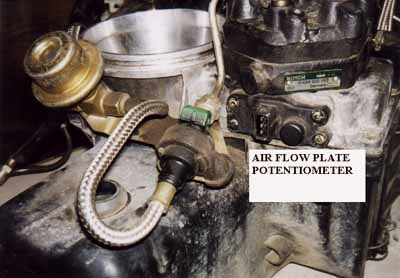
The potentiometer is mounted in the outboard side of the air flow meter assembly, which is under the fuel distributor. The electrical connections are hard to get to on this potentiometer because the electrical connector is located under/behind the fender area. Removing the right front fender liner may allow you to get to these wires. You may also be able to remove the one 13mm bolt that retains the air filter housing and move the housing toward the engine to gain access to this wiring harness. You will have to cut off the plastic wiring sheath to allow connecting to these wires.
Here is a picture of the potentiometer with the CIS air filter box and air flow meter assembly removed from the car.
MEASURING THE POSITION OF THE AIR FLOW METER PLATE
The electrical connector has 3 terminals, with a brown colored wire, a gray wire with black stripe, and a gray wire with a blue stripe. You want to connect the Digital Multi-Meter (DMM) to the brown (ground) and the gray/black wire. Set the DMM to read DC Voltage, ~5 volt scale.
After connecting the DMM to these two wires, un-clip the air filter housing cover and pull the cover off a little to allow your hand to go into the housing so you can manually push up the air flow meter plate.. With the ign. key on and the engine off, push the air flow plate up by hand to the top of its travel (max air flow) while you watch the voltage reading on the DMM. On my 1989 200TQ the voltage output was 4.465 V. On my 1987 5000TQ the max voltage output was 4.38 volts with the ignition key on, and manually moving the plate up to max travel. On my 1989 200TQ with the engine at idle the voltage output was 0.135 V.
To check the amount of travel your air flow meter plate moves while under boost and near redline in 3rd gear, you will need some long DMM cables to reach into the car. I routed the DMM/cables from under the hood near the windshield and then inside the car through an open windrow. With an assistant in the passenger seat watching the DMM, we went for a test drive.
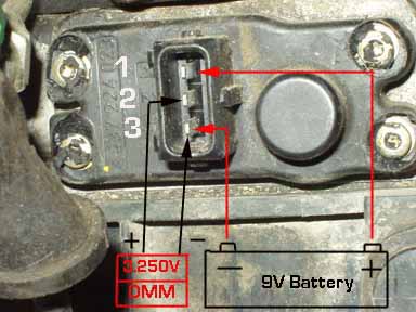
Road test on 1989 200TQ (Ambient temperature was ~60 degree F). I drove the car in 3rd gear at full throttle all the way to redline on a flat road. I had the DMM set to record Min/Max voltages and a boost transducer/DMM to record the max boost. I drove the car to redline in 3rd gear and the airflow plate rose up until the voltage read 4.216. Max boost recorded was 1.79 bar absolute. The air flow plate is close to the end of its travel. TURBO ENGINE TRANSPLANT TESTING If you have transplanted a MC engine into your 4000Q or other Audi, and you don't have the trip computer connected to this air flow meter potentiometer, you can measure the voltage signal from this Air Flow Plate Potentiometer. Use some long wires routed inside the car to connect a 9V battery as shown below, along with a Digital Multi-Meter, or DC Voltmeter to measure the voltage as your partner drives the car under load from 4000 RPM to redline in 3rd or while in 4th gear on an approved race track with no traffic issues.
If you have connected everything correctly, you should see the voltage reading from approximately 0.00V with the engine off, and then higher voltage readings as you manually move the air flow meter plate upward toward the top of its travel. You should check the voltage output and make note how high the voltage goes when you manually push the air flow plate to the end or top of its travel.
Then your partner should watch the voltage reading and the tachometer reading while you drive the car under load, and have them note the voltage readings, as you approach redline in 3rd gear to find out whether you are actually topping out the air flow meter.
OTHER TEST RESULTS
On my 2850lb 1987 5000TQ track car, I did this test with my data acquisition system connected to record the air flow plate potentiometer voltage readout while I drove the car to redline in 3rd and 4th gear. The ECU in this car uses a 2.5 bar pressure sensor and the boost maps are set to make 2.15 bar (16psi) in the mid range. Driving the car in 3rd gear the data acquisition recorded that the air flow plate was topping out at 4400 RPM. When running a 1.8 bar ECU in this car, the air flow plate was topping out around 5500 RPM in 3rd gear.
When the air flow plate tops out, it means that the CIS fuel plunger inside the fuel distributor is not rising up any more to expose a larger slit area at the plunger, and therefore it will not provide any additional fuel above these RPM points.
I richened up the fuel mixture on the above mentioned 1.8 and 2.2 bar ECU's at the higher boost and RPM levels. I increased the duty cycle settings which are programmed in the ECU boost enrichment fuel maps. These map settings change the variable duty cycle signal that drives the CIS frequency valve (solenoid) which is used to change the differential pressure across the plunger slit opening which changes the amount of fuel delivered at the injector.
Many Audi enthusiasts report running their 5000TQ and 200TQ 10V engines with the stock CIS system at boost levels above 2.0 bar absolute with no problems, but I believe that the majority of these engines are topping out their air flow plates at the higher RPM levels. These engines can likely handle the leaner mixture for short duration, and would only create excessive heat in the combustion chamber under sustained high RPM conditions in 3rd or 4th gear.
I do know of a few folks that did their own boost modifications to run above 2.0 bar who had blown headgaskets and damaged a piston under sustained high engine speed operation at elevated temperatures. There are also a few cases of exhaust valve failure during sustained high RPM driving during track events that may have been caused by a lean mixture. Excessive exhaust guide wear can also cause overheating of the exhaust valve head and cause the head to break off and damage the engine. Audi recommends that you do not grind the exhaust valves on the 10V turbo engines, only lapping is permitted. When doing an engine overhaul on high mileage 10V engines, replacing the exhaust valve guides and the exhaust valves is a good idea.
If you are unsure whether your high boost levels are risking damage to your engine, take the time to measure the air flow plate movement and find out if you are pushing the limit of your CIS fuel system.
Most turbocharged engines run overly rich mixtures at air fuel ratios around 11.0 to 1 to reduce the exhaust temperature and reduce the heat load on the engine. These richer mixture settings are required for longevity and are well below the so called "ideal" 12.6 to 1 air fuel ratio for making maximum engine power. The latest generation Audi V6 Bi-Turbo engine uses exhaust temperature sensors upstream of the turbochargers to maintain the exhaust temperature at 980 degrees Celsius (1796F). According to Audi exhaust temperatures exceeding 1000 degrees Celsius (1832F) for long periods can damage the exhaust manifolds and turbocharger.
MC ENGINE AIR FLOW METER and FUEL DISTRIBUTORS
The later dual knock sensor MC engine does show a different air flow sensor plate assembly than what was used on the earlier Single Knock sensor MC engine (86-88 5000TQ, early 89 200TQ). The air flow meter assembly from a 86-88 5000TQ has these numbers, Bosch # 0438 121 053, Audi # 034 133 353D. The later MC engines like the one used in my '89 200TQ's have a different air flow meter assembly, Bosch # 0 438 121 064, Audi 034 133 353L
The Dual knock MC uses the Bosch # 0 438 100 153 Fuel Distributor and the single knock sensor MC engine uses the Bosch # 0 438 100 147 Fuel Distributor.
It would be useful to take a closer look at these two air flow meters and compare them to see if the later version has a different flow capability or just possibly uses a slightly different cone shape for tighter emissions control.
The travel of the air flow sensor plate is not linear, if you look at the shape of the funnel, the slope of the sides change to enrich the mixture off idle and then leaner during cruise and then rich again at the highest settings that occur under full load and high boost. The air flow meter Cone has steeper wall sections at the bottom and at the top which means when the plate is located in this steeper section of the cone, for a given increase in air flow, the air flow plate/fuel plunger will move higher and provide a richer mixture for off idle conditions and for full throttle/load conditions. Stated another way, if the air flow plate was in the middle section of the cone with a more gradually sloped wall section there would be less movement of the air flow plate/fuel plunger for a given increase of air flow.
The linear relationship is only between the movement of the air flow plate and the movement of the plunger in the fuel distributor. The resistance change in the lever potentiometer is also nonlinear with the movement of the air flow plate. The resistance rapidly changes at first during the initial 5 degrees of lever movement, then increases more slowly from 5 to 18 degrees of movement. MEASURING THE LIMITS OF THE STOCK CIS FUEL SYSTEM
It would be useful to understand the limits of the stock CIS with the air flow plate topped out. Inserting the injectors into their own graduated cylinder to measure the amount of fuel in cc's at WOT would be a useful exercise. If you run the ECU output test to start the fuel pump and cycle the frequency valve at 50% duty cycle, this test can could be done. The air flow plate could be pushed up by hand after removing the air filter cover. It would also be interesting to run this same flow test when running different duty cycle settings (50%, 60%, 70%, 80% and 90%) at the CIS mixture frequency valve. This would require some programming changes in the ECU EPROM to set the OUTPUT test duty cycle to 60, 70, 80, or 90 during the test.
One European web site indicates some fuel flow rates for the fuel distributors used in the MC engine. The Dual knock MC uses the Bosch # 0 438 100 153 and the single knock sensor MC engine uses the Bosch # 0 438 100 147. Both of these fuel distributors are shown to flow 202cc fuel per 60sec. I assume this is with a 50% duty cycle at the mixture frequency valve at WOT, but the web site does not clarify this..
202cc's/min isn't that much. FUEL PUMP VOLUME DELIVERY LIMITS? One other aspect of this question regarding the limits of the CIS Air Flow meter and fuel distributor, are related to the limits of the stock MC 10 valve engines Fuel pump to deliver enough fuel at the required pressure. The Bentley shows a volume test, where you should see a flow of 760cc's/30seconds with 12V measured at the fuel pump. With 10V at the pump, 450cc's/30second is the requirement.
The 20V Turbo Engine (3B designation) used in the 1991 200TQ, shows a fuel pump flow test requirement of 650cc's/15 seconds with 12V measured at the pump. With 10V at the pump the requirement is ~480cc's/15 seconds. This is almost double the volume output of the MC engine fuel pump. But, keep in mind the 20V engine uses electronically controlled injectors that use a lower system pressure. Using the 3B fuel pump may not be a bad idea for the higher HP 10 valve MC engines with increased fuel requirements, but it may not be suited for the 6 bar system pressure requirements.
It might be useful to connect a fuel gauge and tape the gauge face to the windshield and then drive the car at full throttle in 3rd gear up to redline and have an assistant check and see if the control pressure or the system pressure drops as you wind out the engine to redline. If the control pressure drops, most likely the system pressure is dropping, and this could allow the air flow plate to move higher than normal and top out early due to the lower control pressure acting on top of the fuel distributor plunger.
The factory sponsored Audi Sport Coupe Quattro A2 rally cars used 2 Turbo Quattro coupe fuel pumps with local relays to make sure they had enough voltage at the fuel pump to supply the higher fuel volume and pressure. These cars used a mechanical Pierburg fuel system, which ran with a system pressure of 10 Bar and is very much like the CIS fuel system, only the fuel distributor plunger was actuated by a custom shaped cam that was actuated by the throttle cable. The system used throttle position, boost and air temp to adjust the mixture. It ran the best when at WOT conditions.
Several fuel injector company websites use the following formula to approximate the fuel injector flow rate requirements based on the Horsepower output of the engine.
Horsepower= (# of injectors) X (Injector flow rate in lb/hour) divided by the BSFC. Injector flow rate in lb/hour can be converted to cc's/min by multiplying by 10.5. Injector flow in cc's/min can be converted to lb/hour by dividing by 10.5
B.S.F.C is Brake Specific Fuel Consumption - In other words, how much fuel you are using per horsepower per hour. In most cases a naturally aspirated engine will have a B.S.F.C of 0.50. This means that the engine will use 0.50 lbs. of fuel per hour for each horsepower it produces.
Turbocharged engines will want to be at 0.60 lbs. per hour or higher.
If we use the 202cc value from the fuel distributor and plug this into the above formula, we get 202cc's/min equals 19.24 lb/hour flow rate.
Then (5 X 19.24)/(0.60)=160.3 HP
Using a 0.50 BSFC, we get (5 X 19.24)/(0.50)=192.4 HP
If the 202cc/min flow number is correct when a 50% duty cycle is applied to the frequency valve, I can only hope that the MC fuel distributor flows considerably more fuel when running higher duty cycles at the frequency valve. The stock MC Engine has an Engine Control Unit which is programmed to make only 1.42 bar absolute boost, and it sets this CIS frequency valve duty cycle to be 68% when under boost. Questions regarding High Performance CIS setups:
One idea is to use a higher flowing air flow metering assembly/fuel distributor from a different make vehicle with a large six cylinder engine and adapting this to work on the highly modified I5 10V Turbo Audis. The tough part is finding a system that will provide the correct fuel while under light cruise conditions, when running manifold pressures less than 1.0 bar absolute (vacuum conditions) and then have enough air and fuel flow range to provide fuel when running over 2.0 bar absolute. The Audi I5 fuel distributor head is cast from a 6 cylinder unit but has one port blocked off. Just a few ideas and thoughts....
May the air and fuel flow be with you. Copyright © SJM Autotechnik™ , all rights reserved
Return to Troubleshooting Tips page. Return to SJM Autotechnik™ main page.
|
| About Us Privacy Policy Terms of Use Links Customer Service Safety Information Home |