|
20V Turbo ECU Fault Code Retrieval,
Anytime an engine problem is occurring, this Fault Code system should be used to first locate any system fault codes that have been recorded. [1] [2] If the vehicle starts:You should drive the car for a minimum of 5-10 minutes and raise the engine speed above 3000 RPM and ensure that the manifold pressure goes above 1.2 bar. You want the engine coolant temp to get above 80C, (176F). You should accelerate at full throttle in 3rd gear to exercise this diagnostic system correctly. If the vehicle does not start: Crank the engine with the starter for at least 5 seconds. After doing the road test or the "No Start" cranking test, proceed to the section below for reading any fault codes stored during this process. SJM Autotechnik: Fault Code Reading
For the 1991 Audi 200TQ 20V with 3B engine, the Black Diagnostic Connector top terminal which is +12V is wired to get its power from Fuse #21 (25A) The lower terminal in this Black Diagnostic Connector is wired to ground
in the Motronic harness.
BLINKING OUT THE FAULT CODES
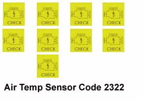
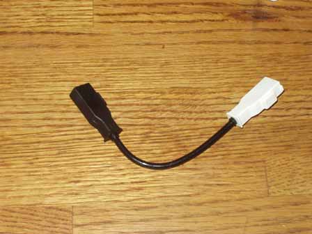
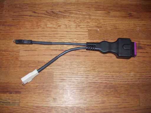
Blink, pause, Blink, pause, Blink, pause, Blink, (2.5 second pause) Blink, pause, Blink, pause, Blink, pause, Blink, (2.5 second pause) Blink, pause, Blink, pause, Blink, pause, Blink, (2.5 second pause) Code 2322 Air temp sensor) would be displayed as follows: In other words..... Blink, pause, Blink, (2.5 second pause) Blink, pause, Blink, pause, Blink, (2.5 second pause) Blink, pause, Blink, (2.5 second pause) Blink, pause, Blink, (2.5 second pause) The sequence of displayed pulses will repeat until the system is stepped to the next fault code stored (if any) by connecting the jumper wire across the connectors again for 4 seconds. The Light will blink once at 2.5 second intervals to indicate that the last error code has been read. Use a note pad to write down the fault codes as they are displayed and then check for the specific fault code description listed in the section below. Check the Bentley Manual for additional information. NOTE: If the ignition is turned on, but the engine is not running and you read the fault codes, you may get a false 2111 or 2112 (RPM and TDC sensors) fault code or 2234 (supply Voltage) fault code. NOTE: The fault code reading procedure will be canceled if the ignition is turned off. CHECK ENGINE LIGHT: IMPORTANT DETAILS: This yellow "Check" engine light will normally come on when the ignition is turned on "if" the bulb is installed in the dash. Diagram courtesy of Audi of America The operators manual refers to this "Check" engine light as the "Emission Control System (ECS) malfunction Indicator Light." Some of the 200TQ's have no "check engine" light bulb installed in the dashboard assembly even though the circuitry is there. Normally this bulb is installed with the wiring and bulb socket in-between the "Airbag" light and the "Door Open" warning light on the right side of the dash and this light should come on when the ignition key is first turned on. I have noticed that some 1990 Audi 200's do not have the location for the CHECK ENGINE Light, and may not have the wiring for this light installed. To install or replace the "Check" engine light bulb, remove the instrument panel lower trim piece and remove the screws holding the instrument panel. Now you can partially pull the instrument panel out on the right side and reach around and install this bulb into the correct twist lock plastic base socket that is located in the Check Engine light socket. The Osram part number for this 1.2w bulb is 2721. NOTE: When you connect an LED across these diagnostic connectors, you will notice that the LED "glows" dimly all the time with the ignition off. The LED glows dimly because a very small current is flowing from the ECU through the LED to the +12V supply when the LED is connected to the diagnostic connectors. This current flow is only 0.4 milli amps, (400 micro-amps), or stated another way, 0.0004 amps. It is probably better to install the Dash mounted "Check Engine" light bulb than to permanently connect the LED across the diagnostic connectors. AUDI Diagnostic Harness 357 971 514E If you have the "Check Engine" light bulb installed, there is also an Audi made diagnostic harness with black and white diagnostic connectors, Audi part number 357 971 514E, that can be used to plug into the diagnostic connectors which acts like a jumper wire to blink out the fault codes. Unfortunately, this little diagnostic harness is expensive, $88 as of Sept 2007
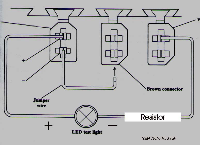
Audi Diagnostic Harness 357 971 514E SJM Autotechnik: Erasing Fault Codes, ECU Fuses: 1991 200 Turbo Quattro with 20V Engine Fuse #27 supplies power to pin 18 of the Motronic ECU for maintaining the fault code memory. You can remove this fuse #27 for a minute or so to erase any stored fault codes. This will also erase any adaptive fuel mixture values stored in the ECU. The ECU will relearn these values after the car has been driven. Fuse #21 supplies the +12V for the black fault code connector underneath the dash as well as the +12V for the Turbo after run coolant pump. Check this fuse #21, if the fault codes do not blink out using the LED. NOTE: The 1991 200TQ 20V engine also has fuse #13 (15Amp) for the fuel pump, fuse #28 (15A) which supply +12V to the fuel injectors and fuse #24 (10A) which supplies +12V to the Waste Gate Frequency Valve, the Idle Stabilizer Valve and the Carbon Canister Valve. Fuse #29 supplies +12V to the O2 sensor heating element on this vehicle as well. If fuse #13, #27, or #28 gets blown.... the engine will not run! The 6 Fuses, #24 to 29 are located under the hood in the fuse box on the "side" rail of the fuse panel perpendicular to the other fuses #1-21. These fuses on the side rail are NOT Spare fuses! Fuses 27 and 28 may be under a small red plastic holder with Motor - Moteur written on top. 1991 200 Turbo Quattro with 20V Engine There is also an "output test" mode that will cycle the engine electrical solenoids on and off to verify they are working correctly. You are able to test the 5 Fuel Injectors Idle Stabilizer Valve (ISV) Carbon Canister Solenoid Valve Waste Gate Solenoid (waste gate frequency valve) NOTE: Fuse #28 supplies +12V to the ECU controlled fuel injectors, and fuse #24 supplies +12V to the Idle Stabilizer Valve, the Carbon Canister Valve, and the Waste Gate Frequency valve, so check these fuses if you suspect a problem with the operation of these components. NOTE: The fuel pump relay supplies +12V to the various engine solenoids : Cold start valve, Frequency (CIS mixture) valve, Waste Gate Solenoid, Charcoal canister solenoid, the after-run control unit, and +12V to the oxygen sensor heating element through the above mentioned fuses. Some have found faulty fuel pump relays with cracked internal solder joints, so check this fuel pump relay if any of these solenoids or devices do not have +12V supplied to them with the engine running. To activate the Output Tests, you must first connect the Jumper Wire across the Fault Code Connectors as shown in the above diagram and THEN turn on the ignition to begin the output tests. DON'T START THE ENGINE. Remove the jumper wire after at least 4 seconds. NOTE: The LED should also be connected so you can see the output test codes blink out, but it does not "have" to be connected to initiate the Output tests.
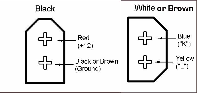
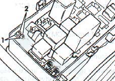
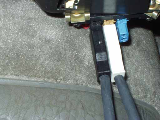
SJM Autotechnik: Fault Code Reading 1992-1996 S4/S6 with AAN 5 cylinder 20V Turbo engine The S4/S6 with 5 cylinder 20V, with the Motronic ECU has a non volatile memory for the fault codes that can be read later even if the car has been turned off after the road test. There should be two connectors grouped together inside the relay box under the hood near the driver side windshield area. Remove the cover off the relay box and you should see two fault code connectors, one Black and one white. 2 shows the rear terminals on the black and white connector, 1 shows the front terminals in the black and white connectors
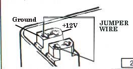
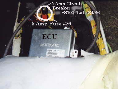
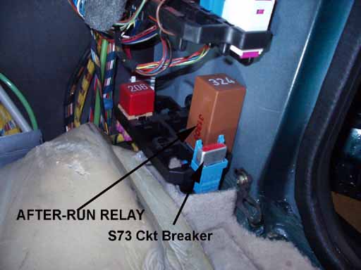
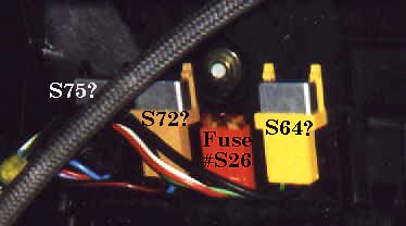
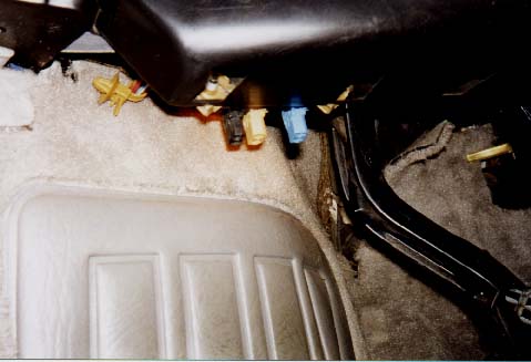
Diagram courtesy of Audi of America Using the Factory VAG1551, VAG1552 or the VAG-COM diagnostic PC interface and software 1992-1996 S4/S6 with AAN 5 cylinder 20V Turbo engine If you are using the VAG-COM PC Interface and Software with the VAS5051/2 twin lead adapter, or the VAG1551 or VAG1552 Factory Scan tool leads, you will insert the black connector lead into the black diagnostic connector, and the white connector lead to the white diagnostic connector. BLINKING OUT THE CODES Using the CHECK ENGINE Light Bulb: 1992-1996 S4/S6 with AAN 5 cylinder 20V Turbo engine A short piece of wire is used to short across the front terminals (1 as shown above) for 4 seconds to activate the fault code sequence Diagram courtesy of Audi of America This fault code reading sequence should be done with the engine running because if the engine is not running you may get a false code (2111 or 2112, RPM and TDC sensors) or 2234 (supply Voltage) code even though there is nothing wrong with these items. If the fault code process does not work, make sure there is +12V and a good ground on the black fault code connector. Fuse #19 on the 1992-95 S4/S6 provides +12V to this fault code connector terminal. These are the same connectors you would use when connecting the factory VAG1551 or VAG1552 scan tool. The "Check" engine light in the instrument panel (dashboard) will blink out the fault codes after the jumper is removed after the 4 second period. The operators manual refers to this "Check" engine light as the "Emission Control System (ECS) Malfunction Indicator Light." (MIL) If the "Check" engine light does not come on with the ignition key turned to the on position, then you may have a burned out bulb in the instrument panel. Some vehicles may not have this bulb installed at the factory. If this is the case, you "may" be able to install a 1.2 Watt instrument panel light bulb (Osram 2721) into the empty socket with wiring behind the instrument cluster . Diagram courtesy of Audi of America As mentioned, with the engine idling, you activate the fault code system by connecting the jumper wire across the two terminals for four seconds and then remove the jumper, the ECU will then begin the sequence to blink out the fault codes. NOTE: The fault code reading procedure will be canceled if the ignition is turned off. Each fault code consists of four groups of pulses. The exact sequence for each code is a start sequence of 2.5 seconds with the lamp on, and 2.5 seconds pause with it off. The codes then follow as a half-second pulse with the Check Engine light on, separated by a half-second pause with the Check Engine light off, with a larger pause of 2.5 seconds between each set of pulses. Example:If no fault codes are stored, code 4444 will be displayed by the ECU flashing the Check Engine Light. The ECU will flash the Check Engine Light on and off as follows after the jumper wire is inserted into the connectors for 4 seconds and then removed. Light on (2.5 sec), Light off (2.5 sec) Now here comes the code 4444 Blink, pause, Blink, pause, Blink, pause, Blink, (2.5 second pause) Blink, pause, Blink, pause, Blink, pause, Blink, (2.5 second pause) Blink, pause, Blink, pause, Blink, pause, Blink, (2.5 second pause) Blink, pause, Blink, pause, Blink, pause, Blink, (2.5 second pause) Code 2322 (Air Temp sensor) would be displayed as follows : In other words..... Blink, pause, Blink, (2.5 second pause) Blink, pause, Blink, pause, Blink, (2.5 second pause) Blink, pause, Blink, (2.5 second pause) Blink, pause, Blink, (2.5 second pause) The sequence of displayed pulses will repeat until the system is stepped to the next fault code stored (if any) by connecting the jumper wire across the connectors again for 4 seconds. The Check Engine Light will blink once at 2.5 second intervals to indicate that the last error code has been read. Use a note pad to write down the fault codes as they are displayed and then check for the specific fault code description listed in the section below. Check the Bentley Manual for additional information. SJM Autotechnik: Erasing Fault Codes: 1992-1996 S4/S6 with AAN 5 cylinder 20V Turbo engine In the early S4's, Fuse S26 (5 Amp) supplies power to pin 18 of the Motronic ECU for maintaining the fault code memory. You can remove this fuse S26 for a minute or so to erase any stored fault codes. This will also erase any learned ignition timing or adaptive fuel mixture values in the ECU. This fuse is located above the Motronic ECU which is located underneath the passenger side floor carpet at the front of the foot well area. In the early S4's, there are two circuit breakers on the left, the 5 Amp fuse to the right, then one more circuit breaker to the right of the fuse. The Carpet may need to be sliced up the left seam with a razor blade, to allow it to be pulled back. The black lower door threshold plastic trim should be removed first, then the right side kick panel before trying to pull back the carpet. It is a pain to get at the Motronic ECU the first time, but gets easier with practice. After pulling back the carpet, there is a black plastic cover over the Motronic ECU and the fuse/circuit breakers. There are two screws that should be removed to get this black cover off. Here is a photo with the carpet pulled back, and the top black plastic cover removed. The later model S4/S6 vehicles accordingly to the Bentley, use a 5 Amp circuit breaker, S102 designation, in the same location, instead of the 5 Amp fuse for this memory circuit. For identifying this S102 breaker, it has a Red wire and a white/black stripe wire connected to it. Removing the circuit breaker for a minute or so, will accomplish the clearing of the memory. SJM Autotechnik: ECU Circuit Breakers: 1992-96 S4/S6 with AAN 5 cylinder 20V Turbo Engine [4] Identifying the ECU circuit breakers I would visually check the color of the wiring used at each circuit breaker and match them to the Bentley wiring diagram colors for the specific year S4 or S6 you have. For the 1992-93 S4, the Bentley shows S64 (15 Amp ckt breaker) with a BK (black) and BK/G (Black with Green Stripe) for supplying +12V to the Ignition Coils. (Later S6 vehicles show the use of S115 breaker with the same wiring colors) 1992-93 S4: The Bentley shows S73 (12 Amp Breaker) with BK (Black) and Y (Yellow) wires, for supplying +12V to the O2 sensor heating element. S73 is shown to be located in Aux Relay Panel III (3), which is behind the right side (passenger) kick panel to the right of the box where the ECU is located.
The kick panel has a screw underneath the plastic plug, and you also need to remove the door sill plastic trip piece and a few screws on this sill trim to allow the kick panel to be pulled out. The kick panel trim extends up the right side of the dash panel and is pulled down/out, so be careful to avoid cracking this plastic panel. 1994-96 Audi S6 shows the same S73 breaker is used for the O2 sensor heating element power supply, but is shown as a 15 amp breaker. It is shown as being in the same location behind the right side kick panel, but with the different wiring colors, white wire coming into the circuit breaker from fuse box supplying +12V, then a Yellow wire going towards the O2 sensor which then turns into a white wire at the O2 sensor connector. Another yellow wire branches off at the circuit breaker and goes to the turbo cooling pump relay/module which should be mounted next to the circuit breaker S73 in the same Aux Relay Panel III. 1992-93 S4: The Bentley shows S75 (12 Amp Breaker) with BL (Blue) and R (red) wires, for the Idle air, Evaporative Canister, and Waste Gate Solenoids. (1995 S6 shows the same S75 breaker is used with the same wiring colors) 1992-93 S4: The Bentley shows S72 (15 Amp Breaker) with BL (blue) and BK/R (Black with red stripe) wires for supplying +12V to the Fuel Injectors. (1995 S6 shows the use of S116 breaker with the same wiring colors) It appears that the same wiring colors were used on the later S6 vehicles, but double check the wiring diagram for your specific year. Different numbers may have been used to designate the circuit breakers. Note: the Bentley uses the German abbreviations for the wiring color codes on the later S4/S6 wiring diagrams. For example: ro is ROT in German for Red, sw is schwarz for Black. Previously the wiring diagram used BK for black, R was used for Red. Here is a close up photo of the circuit breakers and fuse on a 1992 S4, with my best guess as to the circuit breaker designations and locations.
1992-96 S4/S6 with AAN 5 cylinder 20V Turbo Engine There is also an "output test" mode that will cycle the engine electrical solenoids on and off to verify they are working correctly. You are able to test the 5 Fuel Injectors Idle Stabilizer Valve (ISV) Carbon Canister Solenoid Valve Waste Gate Solenoid (waste gate frequency valve) To activate the Output Tests, you must first connect the Jumper Wire across the Fault Code Connectors as shown in the above diagram and THEN turn on the ignition to initiate the output tests. (DON'T START THE ENGINE) After the ignition is turned on, remove the jumper wire after at least 4 seconds.
SJM Autotechnik: LED "Test Light" Construction, for blinking out fault codes. 1991 200TQ The LED with a series resistor is normally connected across two terminals on the fault code connectors. The LED normally needs a resistor in series to limit the current, most LED's operate with 10-30 milli-amps (0.010 to 0.030 amps). A 1/4 watt 680 ohm resistor works pretty well but you don't have to use a resistor with exactly 680 ohms. The current that is flowing through the LED test light circuit is calculated as follows: Charging system voltage minus voltage drop across LED, divided by the resistance (14 Volts - 1.2 Volts)/680 = 18.8 milli-amps (0.0188 amps). The lower the value of resistance, the more current that flows and the brighter the LED, up until the point the smoke gets out. Radio Shack may have a ready to go LED test lamp which already has the resistor in place to limit the current. Look for Radio Shack Catalog No. 276-084A If not they should have the necessary components to build this LED test light. There are some newer "Super bright" LED's that some electronic supply houses carry that should work great in this application. Here is a diagram that illustrates the connection of the resistor in series with the LED.
Diagram courtesy of Audi of America I normally use two different colored wires (black/red) as the LED is polarity sensitive, the flat section on the LED lamp is normally the negative connection. Bolt lug terminals (U shaped) with one leg trimmed off, can be crimped on the wire ends to allow easy insertion into the fault code connector terminals. It won't hurt it if you connect the LED backwards, it just won't make any light.....the resistor can be connected in series on either the + or - wire to the LED. References: [1] [4] Audi of America service training publication: "The New 20V Turbo Engine for the Audi 200 Quattro" "Motronic Engine Management System for the Audi S4 and the 4.2 liter Audi V8" All rights reserved. Copyright © SJM Autotechnik™ , all rights reserved Return to Troubleshooting Tips page. Return to SJM Autotechnik™ main page. |
| About Us Privacy Policy Terms of Use Links Customer Service Safety Information Home |
 VAS5051/2 cable adaptor