|
1992-94 Audi S4 AAN 5 Cylinder 20V Turbo Timing Belt Replacement Information and Photos In addition to "first" reading the Bentley Repair Manual
information,
Other warnings and scare tactics. You can easily bend some of the valves in the cylinder head if you don't get the timing belt set up correctly, so this repair should not be taken lightly.
The AAN engines are also considered "interference" engines, meaning that if the timing belt breaks with the engine running, some of the valves in the cylinder head will hit the pistons and get BENT!
The main thing to keep in mind, when replacing the timing belt, is that you want to have the engine rotated to the correct position (TDC for Cylinder #1) BEFORE you loosen the tensioner pulley and remove the old timing belt.
DO NOT rotate the camshaft or crankshaft by itself unless the timing belt is installed and tensioned correctly so they both turn in unison.
NOTE: Some S4/S6's have an additional washer between the Crank Pulley (Vibration Damper) and the crankshaft.
According to the Audi parts information.
Audi part number (034 105 193) WASHER MAY ONLY BE FITTED IN CONJUNCTION WITH VIBRATION DAMPER 054 105 251J.
WITH VIBRATION DAMPER 054 105 251H THIS WASHER IS NOT REQUIRED.
The following information isn't everything you need to know, but it will help you from freaking out too much when doing this for the first time. Good luck!
Removing the front bumper is recommended, but you must first remove the lower engine tray, there are several quick release metal screws underneath holding this plastic tray as well as some plastic quick release screws on each side connecting this tray to the fender liners. You may also need to first remove the lower grill pieces and the temperature sensor clipped inside the bumper area.
The front bumper is held on with only two allen bolts underneath the front edge of the bumper. The bumper wings on each side, need to be pushed down and pried around the fender liner before pulling the bumper straight off.
The upper bumper trim (Left and right) can be removed using a 10mm socket driver from underneath.
The upper sheet metal piece (lock carrier) that holds the hood latch should be removed, There are several 10mm head screws and the upper radiator bracket bolts that need to be removed. You can leave the hood latch cable attached and just swing this lock carrier sheet metal piece to the rear and lay it across the engine. You will be also removing some other headlamp trim pieces to allow the radiator to be swung outward on the passenger side. The air intake nozzle below this sheet metal should be removed as well.
Remove the lower headlamp trim, you need to first remove the headlamp washer nozzle head by pulling it straight off the plastic tube. You can pull the washer head out against the spring tension with it still inside the tube, then hold the tube while gently twisting the washer head while pulling it off.
Now the lower trim piece and attachment bracket can be removed. The trim has one Phillips screw holding it on, then the trim is pulled toward the center of the car to unhook the outer end. The small trim bracket on the inside should also be removed to allow the radiator to swing past this area.
You should drain the coolant out of the radiator using the drain petcock on the lower passenger side of the radiator. Remove the coolant reservoir cap to allow most of the coolant to drain out.
The radiator will now be swung out on the passenger side to make it easier to access at the timing belt. You can also carefully remove the upper radiator hose from the upper radiator neck if you want.
Loosen the lower radiator mount nuts/washers on each side. A shelf bracket bolted to the bumper shock mount can be used to support the radiator. See below.
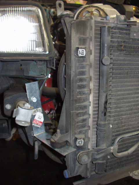
A simple shelf bracket was used to support the radiator and allow it to be swung out for better access to the front of the engine. 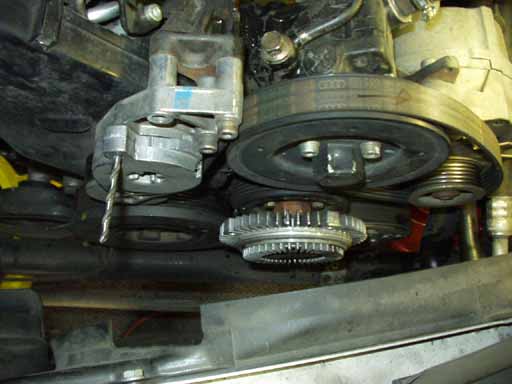 After the radiator was swung out on the passenger side, here is a view down the front of the engine, showing the removal of the engine driven fan blade assembly, there are four 10mm bolts holding this plastic fan to the fan clutch assembly. Removing the fan clutch assembly is not necessary. Before loosening the serpentine belt, you should break loose the three 6mm allen bolts holding the power steering pump pulley to the pump. The serpentine belt tensioner can now be twisted with a large adjustable crescent wrench to loosen the belt tension, a drill bit was then inserted into the hole in the tensioner and tensioner bracket to hold the belt tensioner in this loosened position.
Before wrestling the belt out, you may want to draw a diagram showing how the serpentine belt is installed to avoid too much thought upon reinstallation. Mark the direction of rotation on the serpentine belt with a felt pen. The tensioner and bracket can then be removed. The power steering pump and bracket will need to be moved out of the way to allow getting the water pump out. The alternator top mounting bolt will also need to be removed. The lower timing cover sheet metal piece can be removed, 2 allen screws hold this in place.
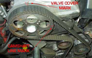
BEFORE you loosen the crank pulley bolt, set the engine to be at Top Dead Center (TDC) for #1 cylinder. To set the engine to TDC for #1, remove the upper cam belt cover, and rotate the engine using the lower crank bolt until the line mark on the camshaft gear, is lined up with the V indentation in the valve cover.
These marks are highlighted red in this photo. Also note that in this photo the engine still needs to be rotated clockwise an additional 1 1/2 turns (540 degrees) so that the camshaft gear will rotate 3/4 of a turn (270 degrees) so that the cam mark is line up at the top with the engine is set correctly at TDC for cylinder #1. Also see photos below for checking the crankshaft flywheel timing mark.
NOTE: It take 2 rotations of the crankshaft for the camshaft to make 1 rotation.
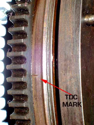
Here is the view of the hole in the transmission on the driver side of the engine compartment that is used to view the flywheel timing mark.
Note: This photo was taken on a car that had the engine removed.
You may need to move some of the engine wiring harness to clearly see inside this hole.
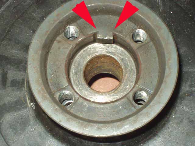
The flat area of the casting inside this hole is used as the reference line for setting the flywheel.
In this photo the flywheel has been removed from the vehicle to highlight this timing mark.
This timing mark can be difficult to see through the hole in the transmission when setting the cam belt timing.
I have found some of these AAN's with incorrectly set engine camshaft timing. This most likely happens after the timing belt has been replaced. The mechanic or technician may have incorrectly used the front vibration damper timing mark, instead of this flywheel mark when doing the repair. For setting the basic engine and cam belt timing, I like to apply some white paint to the mark to make it easier to see.
Before loosening the lower crankshaft bolt, and removing the crank pulley and timing belt, I recommend breaking loose the camshaft gear bolt first ,so you can later remove the gear and replace the camshaft front seal. If you decide not to replace this front cam seal, you can skip this step.
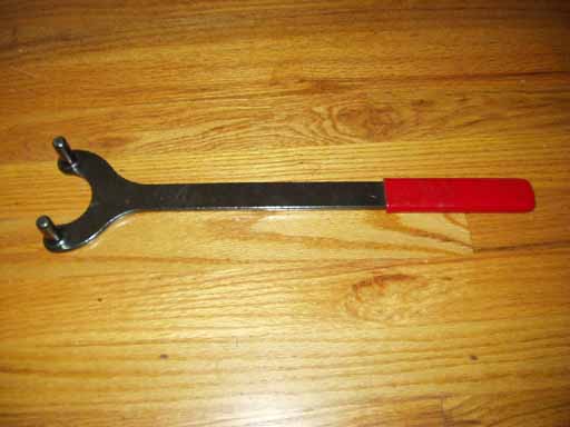
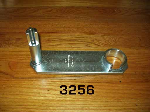
I use a generic cam gear holding tool sold by Mac Tools as shown here. In some cases, the hardest part of this job, is loosening the crank pulley bolt and the cam pulley bolt. I recommend that you borrow or purchase the special Damper Pulley locking Tool # 3256. NOTE: This 3256 tool is unique to the 1992-95 S4/S6 with the AAN designated engine, and is different than the 2084 tool that is used on the earlier 1986-91 Audi 5000/200, both 10V (MC) and 20V (3B designated) engines.
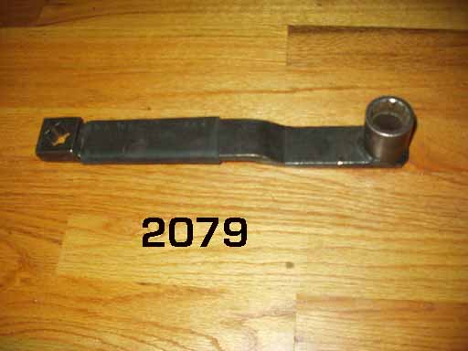
There is also the Crank Damper pulley bolt extending wrench 2079 this is normally used on this job. This 2079 wrench is not absolutely necessary if you decide to use a conventional 27mm socket and long 3/4 inch drive breaker bar. Either way you need to have a long 2-3 foot long 3/4 inch drive T bar or breaker bar and many times will need to add a cheater extension pipe over the 3/4 drive bar to break this crank bolt loose. 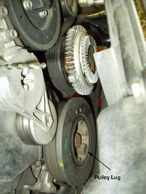
Here is a close up showing the crank pulley, note the lug in the inner part of the pulley. This lug is what gets locked using the 3256 crank holding tool 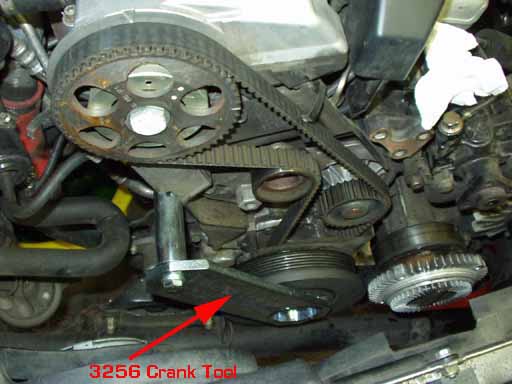
Here is a view of the 3256 crank holding tool installed and bolted to the engine block.
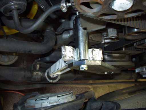 I like to add some additional support for the 3256 tool when loosening the crank bolt. I don't feel that the 10mm thread size bolt threaded into the engine block is sufficient to hold the crank pulley from turning when breaking loose this bolt.
Often times it takes much more than the specified 332 ft lbs of torque to get this bolt loose.
In this case I used part of a jack stand wedged between the lower support bar and the crank holding tool boss, to give more support.
I had a 3 foot breaker bar and it took all I had to break it loose. The bolt has some thread locking compound on the threads and the shaft which should be wire brushed off before re-installing.
If this is the second time you are replacing the timing belt, replacing this crank bolt certainly couldn't hurt while you are in there, as some have reported this bolt breaking after several timing belt replacements were done. The torque spec 'using' the 2079 crank pulley bolt wrench is 258 ft/lbs. Without this 2079 tool the torque spec is 338 ft-lbs.
If you have "loosened" but not yet removed the crank pulley bolt, you can remove the crank holding tool and rotate the engine so the timing marks are lined up and the Engine Timing is at TDC for Cylinder #1.
Now you can loosen the three 10mm bolts that hold the tensioner pulley bracket in place, and relieve tension on the old timing belt and slip it off the camshaft gear and from around the water pump.
Remove the crank damper pulley along with the lower timing gear and belt.
You do not need to remove the 4 small 6mm allen head bolts.
NOTE: The crank damper pulley on the S4/S6's can get stuck on the end of the crankshaft even after removing the large crank bolt. You may need to slowly wiggle it loose by grabbing it with both hands and rocking it back and forth. I like to leave the crank bolt in place but very loose to avoid having the bully crashing into the radiator when it finally comes loose. Inspect the lower timing gear woodruff key as shown below, as I have found many of these broken or with hairline cracks near the keyway.
While you have the damper pulley off, you should visually check out the internal rubber ring for excessive cracking. The damper pulley internal rubber ring condition and characteristics are important for reducing crankshaft torsional vibration.
Remove the water pump bolts and water pump housing. Have a pan ready to catch the coolant that will spew out.
It is a good idea to scrape clean the water pump O-Ring sealing surface, using some wet/dry 400 grit sandpaper can also clean this surface up. If the surface of the engine block is badly rusted and deeply pitted, you may want to sparingly use some high temp silicone sealer on the surface when installing the pump.
The tensioner pulley can be replaced by unbolting it from the tensioner pivot bracket, then install the new pulley with some blue medium strength loctite on the bolt threads and torque to 15ft-lbs. Replacing the front crank seal:
Replacing the front crank oil seal isn't easy as the seal diameter is close to the size of the crankshaft snout. Before removing the seal, note how deep the seal is installed into the front housing.
One way to remove the crank seal, is to carefully use a sharp awl and center tap the outer edge of the metal seal and then carefully drill a small hole into the metal edge of the seal. Now you screw a small sheet metal screw into the drilled hole and then lever out the screw using pliers or side cutters to pop out the seal edge. Sometimes with stubborn crank seals, you need to drill on both sides of the seal and install 2 screws to pop it loose. It is often difficult to get a nice hole clean hole on the outer edge of the seal. Be sure to keep any metal shavings out of the area behind the seal.
NOTE: This crank seal removal trick isn't for everyone, so you may want to rent or purchase the official Audi tool 3203 designed for removing this small diameter seal.
Installation is a little tricky, but is made much easier if you use the factory plastic tool 2080A to push the new seal in using the 2080A and the crank bolt. The 2080A is not very expensive <$20 and worth getting to save you grief. I don't usually use the protective sleeve provided, instead I carefully slide the seal over the end of the crank until it clears the sharp edge, then use the 2080A tool to push it home.
If you don't have the 2080A guide tool , you will you need something which will fit over the end of the crankshaft snout and which is slightly smaller in diameter than the outer seal rim. In some cases a 1/2 drive socket or a piece of cut pipe can be used for this. The crankshaft front seal part number is normally 034 115 147A.
Lubricate the inner seal lip as well as the outer edge on the seal with engine oil before installing. You don't need much oil on the outside edge, just enough to allow it to slip into place without too much force. Use the 2080A tool and the crank pulley bolt to draw in the new seal until the tool bottoms out. With the 2080A tool in place, you can turn the crank pulley bolt with a socket only using your hand, or you can use a short adjustable wrench to turn the crank bolt and draw this seal in place. It should not take much force to pull the seal in.
If you don't have the 2080A, use the correct size socket and hammer to carefully push or tap in the seal. You can also use the crank pulley bolt and a large washer over a short piece of pipe of the correct size to slowly draw in or press the new seal in place. It should go in very easy.
The camshaft front seal can be replaced in a similar manner as described above, although a different size socket or tool will need to be used. I use an old front wheel bearing inner race with a large washer along with the cam gear bolt to draw in this camshaft front seal.
Note that the crank and cam seals are slightly different sizes and can easily be confused.
The Camshaft seal normally has a slightly smaller Outside and Inside Diameter than the crankshaft front seal.
Install the crank pulley/gear and new timing belt over the crankshaft snout. Wire brush the crank bolt to remove the old Loctite from the shaft and thread area, then install the crank bolt with blue medium strength Loctite on the threads and bolt shaft area and temporarily hand tighten the bolt.
Install the lower shield over the crank pulley, this can be a pain to get it back in there if you install it later after the water pump is already installed.
Install the camshaft gear and hand tighten the camshaft gear bolt.
I also like to put a small amount of blue Loctite on this camshaft gear bolt threads.
At this time only hand tighten the camshaft gear bolt.
The water pump O-ring can be glued into the groove in the water pump to prevent it from coming out if it won't stay in place. This avoids getting the O-ring pinched against the pump and the engine block as you install the water pump.
Install the new water pump and power steering pump bracket and torque the water pump bolts to 15 ft lbs. You can also install the tensioner bracket with the new tensioner pulley. I like to put some blue medium strength loctite on these small tensioner bolts but only hand tighten them at this point.
Replacing the thermostat and O-ring at this time is a good idea.
Slide the new timing belt over the cam gear and water pump keeping the belt tight on the right side. Double check the cam dot/line location against the valve cover V mark, and that the crankshaft TDC mark is still lined up on the flywheel against the transmission casting reference mark.
You may have to rotate the crank pulley slightly to get the timing belt over the cam gear.
Rotate the tensioner bracket upwards to put some tension on the timing belt. Don't get crazy with the tension on the timing belt, normally the thing is a little loose when the engine is cold and you should be able to easily twist the belt 90 degrees with your fingers.
Check the tension by rotating the engine counter-clockwise a little and then do the 90 degree rotation test on the slack side of the belt. If you get the belt too tight, it will make a whirring or whining sound when you rev the engine.
Torque the crankshaft bolt to 258 lb-ft using the 3256 holding tool and correct pulley wrench extension tool 2079, or use a regular 27mm socket and torque to 332lb-ft.
Some tool rental companies have large beam type torque wrenches to torque this correctly.
Now that the timing belt is installed and the crank pulley is torqued, you can fully tighten the cam bolt using the holding tool and torque to 48 lb-ft.
Now slowly rotate the crank pulley around 360 degrees and double check the crank TDC line mark and the cam gear line and valve cover V mark alignment AGAIN.
Rotate the engine over several revolutions and then check the timing belt tension again and adjust the tensioner if necessary. The tensioner bracket small bolts only get torqued to 7 lb-ft, so take it easy on these.
You can finish up re-installing the other components. After all the cooling system components and hoses are connected, and the radiator drain petcock is closed, I like to fill up the block and head with coolant through the top radiator hose, then install the top hose onto the radiator neck, and complete the filling through the coolant reservoir. I use the Pentosin Blue non-phosphate coolant, three of the 1.5 liter Pentosin coolant bottles work well given that the cooling system holds 9 liters total.
MAKE SURE YOU HAVE TORQUED THE CRANK AND CAM PULLEY BOLTS! 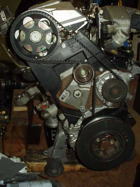 Here is a view of the AAN engine showing the timing belt, water pump and belt tensioner with the front pulley installed.
The timing mark is NOT lined up correctly in this photo Copyright © SJM Autotechnik™ , all rights reserved
Return to Troubleshooting Tips page. Return to SJM Autotechnik™ main page.
|
| About Us Privacy Policy Terms of Use Links Customer Service Safety Information Home |