|
1992-96 Audi S4/S6 Ignition System Details and Troubleshooting
The common misfire problems under load when the boost is increasing are usually caused by either a problem with the spark plug(s), one or more of the ignition coil connector leads, or from one or more defective ignition coil(s). In less often cases, the Power Output Stage can also cause an intermittent misfire under load, so don't rule it out. I also recommend checking and/or replacing your fuel filter, as a plugged filter can often feel like an engine misfire under high boost levels. Ignition misfires that happen all the time are most often caused by a defective Power Output Stage (POS) that has one or more defective drivers used for a particular cylinder. Swapping the two POS units can sometimes locate the defective POS if the location of the misfire changes after the swap. Also keep in mind that there have been cases where the ignition coil(s) fail all the time, i.e. at engine idle, cruise, and under load. Keep in mind that it is also possible for the Power Output Stage (POS) to have an intermittent failure for one or more cylinders that only happens during driving which can make it difficult to locate by the swap method. This may only happen when the POS gets warm/hot during normal operation or under extreme cold conditions. Poor heat sink conduction from the back of the POS to the metal bracket
may cause thermal shutdown problems when the POS gets warm/hot. The S4/S6's that are running higher boost levels seem to be more prone to ignition system problems as they are trying to provide a spark under very high cylinder pressures.
Trouble-shooting these ignition misfires can be tough as the problem may only occur under load and/or high boost conditions.
It can be difficult to locate which cylinder spark plug, coil connector
lead, ignition coil or the particular intermittent POS that is causing
the misfire problem under load.
One suggested method is to remove one fuel injector connector at a time and see if the misfire behavior changes when driven under load.
Ignition System Description:
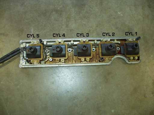
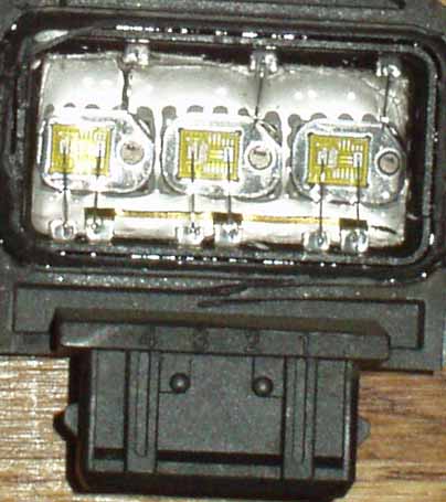
The Ignition coils are mounted individually in the top section of the valve cover.
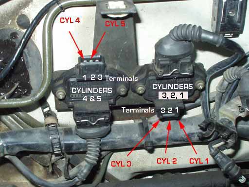
Ignition Coil Power Output Stages (POS) The System use two ignition coil Power Output Stages (POS). The Engine Control Unit (ECU) sends 5 separate control signals (one for each cylinder) to these 2 Power Output Stages which are used to supply the higher current needed to accurately turn on and then off the Ignition Coil to produce the high voltage ignition spark.
The Left POS is used for Cylinders 4 and 5, the Right POS is used
for Cylinders 3, 2 and 1 If the misfire is happening all the time, even at idle, consider yourself lucky. You can remove the fuel injector electrical connectors one at a time with the engine idling and see if one cylinder has no change in idle speed or idle quality when the fuel injector is unplugged.
If you locate a misfiring cylinder this way, you can then swap the two Power Output Stages and see if the misfiring cylinder location changes which will tell you that one of the POS units is causing the problem.
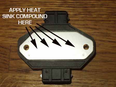
The modules have Phillips screws with a nut on the back, holding them to the bracket on the firewall. The entire bracket with the two POS can also be removed, by removing the two 10mm nuts inside the plenum area under the plastic cover.
You may want to get some Heat Sink compound from your local electronics
supply store to apply to the back of the POS module to increase the
heat transfer between the POS and the metal bracket for improved cooling.
After swapping the two POS's, restart the engine and remove the fuel injector connectors one at a time to locate which cylinder is now missing.
If the misfire goes away completely, then you most likely had a misfire on cylinder #3 in the original Right side POS, and now the unused channel (Terminal 3) from the Left POS is being used to drive Cylinder #3 with the Left POS being moved to the Right POS position.
If the misfire moves to another cylinder by 3 locations. If the misfire moves from Cylinder 5 to 2, then the Left Side POS driver for Cylinder 5 was defective. If the misfire moves from Cylinder 4 to 1, the Left Side POS driver for Cylinder 4 was defective. If the misfire moves from Cylinder 2 to 5, then the Right Side POS for Cylinder 2 was defective. If the misfire moves from Cylinder 1 to 4, then the Right Side POS driver for Cylinder 1 was defective.
If the misfire moved to cylinders 3, 2, or 1, then you should return the modules to their original positions and this indicates the left POS was the defective one and you may be able to rewire the input and output connections to utilize the one unused channel in this left POS.
If the misfire moved to cylinders 4 or 5, then your right POS was
defective and you may be able to rewire the two connectors on the Left
POS to utilize the one unused coil driver on Terminal 3 from the original
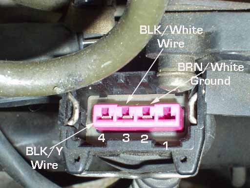
Right side POS. This is the lower connector on the Left Side POS. The BLK/Y wire should be for Cylinder 4 The BLK/White wire should be for driving Cylinder 5. The BRN/White stripe wire is the ground for the POS.
Depending on which channel is defective, either one of these wire terminals can be inserted into the blank terminal opening after disassembling the connector housing to utilize the 3rd channel that wasn't being used previously.
The upper Connector on the POS that goes to the Cylinder 4 and 5 Ignition Coils also needs to have the appropriate terminal for cylinder 4 or 5 moved into the unused terminal location depending on which cylinder is being moved to the unused 3rd channel.
After the offending POS channel is identified you will end up with one 3-channel POS and one 2-channel POS. The 3- channel one goes on the right (looking at the firewall) for cylinders 1, 2, & 3, with the top & bottom harnesses plugged in normally. The 2-channel one goes on the left for cylinders 4 & 5. Swap the wires/terminals (if necessary) in the top & bottom harnesses for the left one to make sure the good 2 channels are now used; the dead one will be blank.
Looking Inside the POS
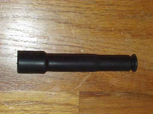
Ignition Coil Connector Lead
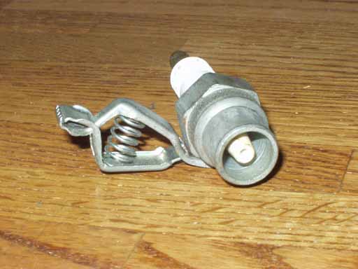
This system uses a ignition coil connector lead between the ignition coil and the spark plug which normally should have approximately 5000 ohm resistance when measured across each end with an Digital Multi-Meter (DMM) in the Ohms setting.
Unfortunately, this resistance test will only help locate a lead with excessively high or low resistance, and won't find the ones that are arcing across the rubber boot to the cylinder head under high loads due to deterioration and breakdown of the rubber boot. One suggested method is to remove one fuel injector connector at a time and see if the misfire behavior changes when driven under load.
You can also swap in a complete set of 5 coil packs from another S4/S6. You can also install one new coil connector lead at each cylinder location, one at a time, and then test drive the vehicle after each swap, to try and locate which cylinder coil lead is causing the problem.
Other Ignition Coil Tests: The Bentley manual describes a test for the ignition coils. You remove the coil pack cover from the valve cover, and lay the coil pack cover on its side with spark plugs inserted into the coil leads. You have an assistant crank over the engine while you watch for spark at the plugs. Note; Disconnect the 5 fuel injector electrical connectors first before doing the crank test. Unfortunately, the spark plugs don't have a wide enough gap
to stress test the coils to locate the defective one that has a weak
output and will only work to show which coil has no output, possible
due to a POS failure. If you suspect that you may have an defective ignition coil that only
fails under high boost conditions, but are not sure if you have an ignition
misfire or fuel related misfire, you may want to find a repair shop
which has a portable exhaust analyzer. Another suggested method is to remove one fuel injector connector at a time and see if the misfire behavior changes when driven under load. If you are unable to locate the defective coil using the above methods,
you may have to swap in a known good ignition coil into each coil position
one at a time and then test drive the car under load/boost until you
locate the defective coil.
Copyright © SJM Autotechnik™ , all rights reserved
Return to Troubleshooting Tips page. Return to SJM Autotechnik™ main page.
|
| About Us Privacy Policy Terms of Use Links Customer Service Safety Information Home |