

|
20V Motronic ECU System 1991 200TQ and 1992-95 S4/S6 with 20V turbo Engine THROTTLE SWITCH-THROTTLE POTENTIOMETER Intermittent Operation-Low Boost and Idle Speed Problems The throttle switch assembly has one idle switch and a potentiometer inside which provide idle and throttle position information to the ECU. This idle switch portion should be tested for continuity (low resistance connection <1 ohm) at idle. On the 1991 200TQ 20V vehicles, I have found that the idle switch can have cracked solder joints inside this throttle switch and cause an intermittent 2121 fault code. The photo shows the inside connections that can crack and cause intermittent problems. If you are careful, you can use a razor knife to cut the plastic top along the seam and pop the top off the throttle switch and then re-solder the cracked idle connections. 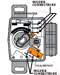 Diagram courtesy of Robert Bosch Corporation Test procedure 1991 200TQ 20V: The potentiometer portion should have the resistance output checked as the throttle is slowly opened and closed. The potentiometer provides a variable resistance output from ~1000 ohms to ~2800 Ohms. There are three connections inside the switch that are soldered that could cause problems on high mileage engines. With the ignition turned off and the connector removed from the throttle switch/potentiometer, connect the ohm meter between pins 2 and 3. Slowly open and close the throttle and note how the resistance value changes. With the throttle closed at idle, the resistance should be ~1000 ohms, at Wide Open Throttle, the resistance will be around 2800 ohms. The actual values at these two positions will depend on how the throttle switch is adjusted. When the throttle switch/potentiometer connector is installed, a 5 volt reference voltage is connected to this variable resistance potentiometer to provide a variable voltage output for the ECU as the throttle is opened and closed. If you pull back the rubber boot on the connector for the throttle switch/potentiometer and connect a Digital Multi-Meter (DMM) to pins 2 (-) and 3 (+), with the ignition turned on, you should read ~0.2 volts with the throttle closed and ~4.6 volts with the throttle opened fully (WOT) . Be careful not to short across the terminals while probing with the DMM. In some unusual cases, an oscilloscope may be required to view the voltage output from this throttle potentiometer to look for any voltage discontinuities or drop outs. These short duration voltage discontinuities or drop outs are often missed by most Digital Multimeters that are used to measure this voltage because they sample the voltage too slowly (4 times/second). These voltage discontinuities or drop outs, can be caused by a worn resistance track or a cracked substrate inside the potentiometer. 1992-95 S4/S6: One S4 Throttle Position sensor I measured, had ~1000 ohms with the throttle closed, and about 2700 ohms at full throttle. Check the Bentley Manual for the other tests using the VAG 1551/1552 or PC equivalent software and interface. The throttle valve potentiometer is only used for boost regulation as the throttle valve position is a reference value for the boost control map. Boost regulation will take place when the throttle plate is open greater than 35 degrees. NOTE: 1991 200TQ 20V: If the potentiometer should fail, boost pressure is controlled mechanically by the wastegate at a lower value than what is programmed in the ECU [1]. [2] 1992-95 S4/S6: Throttle Position signal is used as a substitute function for a failed MAF sensor and is used for diagnosis of the closed idle switch. Self diagnosis recognizes two faults, short to ground (signal too low) or short to Positive (signal too high). If a fault is detected, a set value of 28 degree throttle opening is used for engine calculations and boost pressure control is shut off. Here is a photo showing the Throttle Switch which is mounted on the rear of the intake manifold behind the main intake pipe on the 1991 Audi 200TQ 20V. 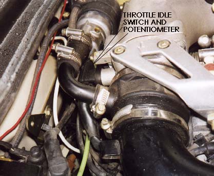
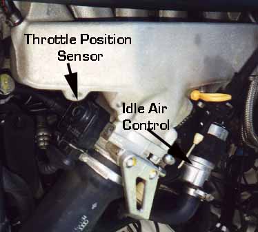 1992-95 Audi S4/S6 Throttle Position Switch/Potentiometer. 1991 200TQ 20V Test Procedure: Remove the Multi-Pin connector to this throttle switch/potentiometer by using your thumb to push on the wire release clip. Use a Digital Multimeter (DMM) to check the idle switch portion for a good low resistance connection (less than 10 ohms resistance) by probing the switch between pin 4 and pin 6 with the throttle closed. Pin 1 is on top of the switch. You should hear the idle portion of the throttle switch "click" as you open and close the throttle. The resistance check should show infinity (very high resistance) when the throttle is opened. 1992-95 S4/S6 Check the Bentley Manual for specific test procedure. Sometimes carbon gets built up on the inside of the throttle plate and this prevents the throttle from fully closing. In other cases some bonehead has used the throttle plate stop screw to adjust the idle speed (WRONG) and this has screwed up the resting position of the throttle plate. Check the Bentley manual for specific throttle plate stop adjustment and idle switch adjustment if this has been altered. Adjusting the Throttle Switch If you don't hear this clicking, you may want to loosen the two 7mm bolts that hold the throttle switch to the throttle body and check the adjustment of the switch. You can do a basic adjustment of the throttle switch by loosening the two 7mm bolts holding the switch to the throttle body and then slowly rotate the switch counter-clockwise until the stop is felt. Tighten the screws while holding the switch against the stop. With the engine off and the throttle closed in the idle position, listen for the clicking of the idle switch as you rotate the throttle open. 20V ECU system information index References: [1] Audi of America, Technical service training publication: "The New 20V Turbo Engine for the Audi 200 Quattro-publication [2] "Motronic Engine Management System for the Audi S4 and the 4.2 Liter Audi V8" All rights reserved. Copyright © SJM Autotechnik™ , all rights reserved Return to Troubleshooting Tips page. Return to SJM Autotechnik™ main page. |
| About Us Privacy Policy Terms of Use Links Customer Service Safety Information Home |