20V Turbo Motronic ECU Photos, Pin Out Information
: 1991 200TQ 20V Motronic ECU Installation
Photo
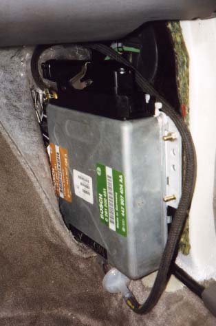
The ECU is bolted to the side panel with two nuts and washers. The front
of the ECU is slid under a bracket. To remove the ECU, remove the two
rear nuts/washers, then the rear edge of the ECU can be pulled inward
off the studs, and then pull the ECU straight back toward the rear of
the car to pull the front edge out from under the bracket.
The manifold pressure hose can then be removed. The ECU harness connector
front lever should be rotated upward to release the harness connector
front edge, then the rear tab can be pulled forward and up and out.
1991 200TQ 20V Motronic ECU Pin Out
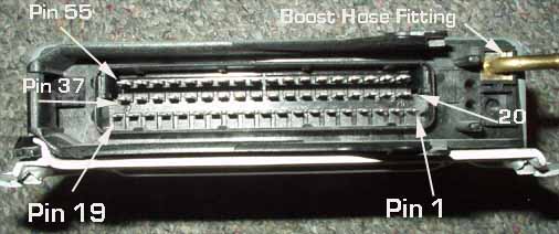
Main ECU connector pin out, 55 pins. When viewing the ECU installed in
the car as shown above, Pin 1 is the first pin on the right, toward the
front of the vehicle. (next to the connector release lever end). Pins
2-19 follow towards the rear on the right side row.
Pin 20 is the first pin in the middle row, toward the front of the vehicle,
with its position shifted slightly rearward of Pin 1. Pins 21-37 follow
to the rear in the middle row. Pin 38 is the front pin on the left row,
pins 39-55 follow toward the rear on the left row.
The left row is the row close to you with the ECU mounted in the vehicle.
Here is a diagram showing the ECU pin out when looking directly at the
ECU as mounted in the car.
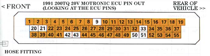
Pin Out of the ECU 1991 200TQ 20V Diagram courtesy of Audi of America
[1]
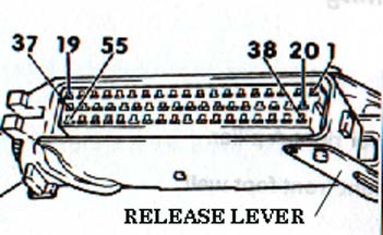
Here is a photo of the wiring harness connector and pin locations.
Diagram courtesy of Audi of America [1]
1991 200TQ 20V ECU Pin Out Signal Description
1. Output stage for Ignition coil (Gray/Red stripe wire)
2. Return signal path (ground) for several components:
Air Temp, coolant temp sensors, Knock 1, 2 sensors,
altitude sensor, throttle position sensor(White/Black stripe wire)
(ECU terminal 2 is also connected to terminal 30 on ECU via harness
welded connection)
3. Fuel Pump Relay signal (Brown/Yellow wire)
4. Idle Stabilizer (White/Yellow stripe wire)
5. Carbon Canister Frequency valve (White/Red stripe)
6. Tachometer/Trip computer (Yellow/black stripe)
7. Mass Air Flow Sensor (Green/White stripe wire)
8. Hall Sender, (signal wire) (Green/White stripe wire)
9. Open, not used (This pin may actually be the Barometric/Altitude
sensor, check your wiring)
10. Ground (Brown Wire)
11. Knock Sensor #1 (shielded coax wire, color unknown)
12. Hall sender, altitude sensor, throttle valve potentiometer and coding
plug (+5V) supply (Red wire)
13. Diagnostic plug connector (L wire) (Brown/Green stripe wire)
14. Control Unit ground (Brown wire)
15. Injector #3 control signal ( - )(White/Violet stripe)
16. Injector #2 control signal ( - )(White/Blue stripe)
17. Injector #1 control signal ( - ) (White/Brown stripe)
18. Terminal 30 (+12V) supply, Fuse #27 (White/Black stripe)
19. Control Unit ground (Brown wire)
20. Open, not used
21. Open, not used
22. Diagnostic plug connector (output) (Green/Red stripe wire)
23. Wastegate Frequency valve (Yellow/Red stripe)
24. Control Unit ground (brown wire)
25. Mass Air Flow Sensor (+ pin 4) (Green/Violet stripe wire)
26. Mass Air Flow Sensor (+ pin 2) (Red/Black stripe wire)
27. Terminal #15 (Ignition +12V) (Black wire)
28. Oxygen Sensor (signal wire, no color shown, but may be green coax
cable)
29. Knock Sensor #2 (white center conductor wire, shielded coax)
30. Ground (Green/Black stripe wire)
31. Boost Pressure Gauge signal for trip computer (Yellow/blue stripe)
32. Trip Computer (Blue/Black stripe wire)
33. Open, not used
34. Injector #5control signal ( - ) (Yellow/Blue stripe wire)
35. Injector #4 control signal ( - ) (Yellow/Green stripe wire)
36. Multifunction temperature sensor Pin R (Blule/Green stripe wire)
37. Voltage Supply input, Fuel injectors, Mass Air Flow Sensor (+12V,
Fuse #28) (Black/Red stripe wire)
38. Coding plug (Gray/Violet stripe wire)
39. Coding plug (Gray/Yellow stripe wire)
40. A/C Compressor (Green/Yellow stripe wire)
41. Idle speed increase signal (A/C on) (White wire)
42. Open, not used
43. Open, not used
44. Intake Air Temperature Sensor (Brown/Blue stripe wire)
45. Coolant Temperature Sensor (Gray/Brown stripe wire)
46. Altitude Sensor (Gray/Black stripe) (This pin may actually
be not used as described by pin 9)
47. Engine Speed Sensor (Gray wire)
48. Ground for reference (62 degree before TDC) and speed (RPM) sending
units
(shown as two wires, one Red, one Blue)
49. Reference (62 degree before TDC) sending unit (Violet wire)
50. Open, not used
51. Open, not used
52. Idle Switch (Violet wire)
53. Throttle Valve Potentiometer (Gray wire)
54. Coding plug (White/Violet stripe wire)
55. Diagnostic plug connector (K wire) (White/Blue stripe wire)
1991 200TQ 20V Motronic ECU Internal
Photos
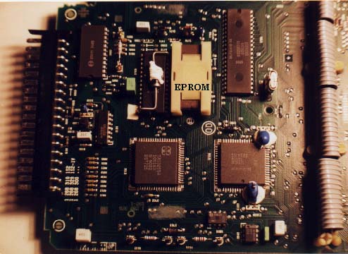
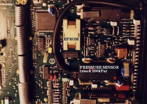
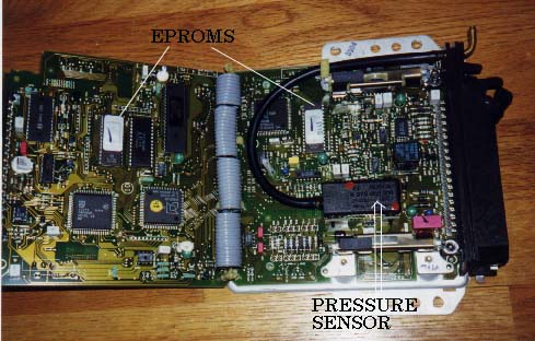
Here is what the inside of the 1991 200TQ 20V Motronic ECU looks like.
The top and bottom circuit boards are shown with the EPROMs and 200kPa
pressure sensor highlighted.
S4/S6 Motronic ECU Installation
photo
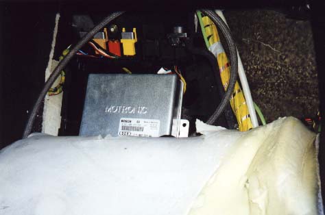
The S4/S6 ECU is a bit of a pain to remove, as it is installed upside
down behind the passenger side floor carpet and behind a plastic cover
(US, European vehicles).
The photo below shows the location in the car with the carpet pulled back
and the plastic cover removed.
To gain access to the Motronic unit, snap the top cover off the passenger
side lower door sill panel and then remove the screws holding the right
side door sill panel.
Also remove the one screw on the right front kick panel in front of the
door sill panel as shown below.
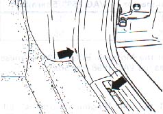
Diagram courtesy of Robert Bentley, Inc.
Pull up the door sill panel so that the right side kick panel can be pulled
out towards the rear. The right side kick panel trim extends up the right
side of the dash so be careful pulling this panel out or you can crack
this side trim. The side trim portion of the kick panel can be pulled
down and out from the dash area.
The carpet needs to be cut with a razor blade in a few places up the seam
on the left side so the carpet and insulation can be pulled down to view
the plastic panel underneath where the ECU is mounted. After pulling down
the carpet, and gaining access to the plastic panel, remove the two screws
holding the plastic cover and pull the cover out.
Then remove the lower plastic panel which has two lower tangs and slides
down into the bottom of the plastic tray. The upper relay mounting strip
may need to be slid back and up out of the way. Pull the ECU out so that
the manifold pressure hose can be removed along with the ECU harness connector.
The ECU harness connector lever should be rotated away from the connector
to release the harness connector edge, then the rear tab can be pulled
forward and out.
S4/S6 Motronic ECU Pin Out
Main ECU connector pin out, 55 pins. With the ECU removed from the car
and looking down at the ECU at the connector end, and viewing the ECU
pins with the hose fitting on the top right, Pin 1 is the first pin down
on the right. Pins 2-19 follow down on the lower side row.
Pin 20 is the first pin in the middle row, toward the hose fitting end,
with its position shifted slightly left of Pin 1. Pins 21-37 follow to
the left in the middle row.
Pin 38 is the front pin on the top right row, pins 39-55 follow toward
the left on the top row.
1992-95 S4/S6 5 Cylinder 20V AAN Engine ECU Pinout
Here is a photo of the wiring harness connector and pin locations.
Diagram courtesy of Audi of America [1]
1992-95 S4/S6 Five Cylinder 20V Turbo ECU Pin Out
Signal Description
1. Power Output Stage (output) signal for Cyl #1 Ignition coil
2. Power Output Stage (output) signal for Cyl #2 Ignition coil
3. Fuel Pump Relay signal (output) (E87)
4. Idle Air Control Valve (output) (N71)
5. Carbon Canister (Evaporative Emissions) Frequency valve (output)
(N80)
6. A/C Control Head (E87)
7. Mass Air Flow Sensor (G70)
8. Hall Sender, (G40) (signal wire-Pin S)
9. Barometric sensor (atmospheric pressure)
10. Oxygen Sensor (G39)
11. Knock Sensor #1 (G61)
12. Hall sender, altitude sensor, throttle valve potentiometer and coding
plug (+5V) supply
13. Data Link (Diagnostic) connector (L wire)
14. Fuel Injectors (N30-83) ground on intake manifold
15. Open, not used 16. Injector #5 control signal, (output) (N83) (
- )
17. Injector #2 control signal, (output) (N31) ( - )
18. ECU Power Supply Terminal 30 (+12V), Fuse #64
19. Shielding for sensors, intake manifold ground
20. Power Output Stage (output) signal for Cyl #4 Ignition coil
21. Power Output Stage (output) signal for Cyl #5 Ignition coil
22. Data Link (Diagnostic) plug connector (blink code output)
23. Power Output Stage (output) signal for Cyl #3 Ignition coil
24. Control Unit ground, intake manifold
25. Mass Air Flow Sensor (output) (G70) (Burn off signal for hot wire)
26. Mass Air Flow Sensor (G70) ground
27. ECU Power supply Terminal #15 (Ignition +12V)
28. Oxygen Sensor (G39) (signal wire in)
29. Knock Sensor #2 input (G66) (Cylinders 4 and 5)
30. Ground for Knock sensor #1 and #2 (G66 and G61), Baro sensor (F96),
Throttle position pot (G69), Coolant Temp sensor (G62), Intake Sensor
(G42), and Coding plug
31. Fuel consumption signal for trip computer (Pin 15)
32. Trip Computer Boost Pressure Gauge signal for (Pin 9)
33. Waste Gate Frequency Valve Ground
34. Injector #3 control signal (output) (N32) ( - )
35. Injector #4 control signal (output) (N33) ( - )
36. Injector #1 control signal (output) (N30) ( - )
37. Voltage Supply (+12V) input with ignition on for all 5 Fuel injectors
(N30-N83), Mass Air Flow Sensor (G70), Evap canister freq. valve, Wastegate
Freq. valve, Idle air control valve ( Fuse #72)
38. Coding plug, Pin 1
39. Coding plug, Pin 2
40. Tachometer
41. A/C on, Idle speed increase signal
42. Open, not used
43. Open, not used
44. Intake Air Temperature Sensor (G42)
45. Coolant Temperature Sensor (G62)
46. Open, not used
47. Reference Sensor, Crankshaft position (input)
48. Ground for Reference and Engine Speed (RPM) sending units
49. Engine Speed sending unit (input)
50. Instrument cluster (G21), Road Speed signal
51. Open, not used
52. Idle Switch inside Throttle Potentiometer switch
53. Throttle Position Potentiometer
54. Open, not used
55. Data Link (Diagnostic plug) connector (K wire)
S4/S6 Motronic ECU Photo Here is what
the inside of the S4/S6 Motronic ECU looks like.
References: [1] Audi of America, Technical service training publication:
"The New 20V Turbo Engine for the Audi 200 Quattro-publication All rights
reserved.
Copyright © SJM Autotechnik™ , all rights reserved
Return to
Trouble-Shooting Tips page.
Return to
SJM Autotechnik™ main page.