

|
20V Motronic ECU System 1991 200TQ and 1992-95 S4/S6 with 20V Turbo Engine ECU COOLANT TEMP SENSOR The Engine coolant temp sensor (two wire connector) is mounted on the back of the cylinder head near the heater valve. See photo below for location info. 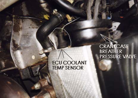 1991 200TQ 20V 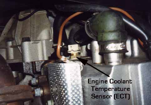 1992-95 S4/S6 The sensor is a Negative Temperature Coefficient (NTC) resistor. This means the resistance goes down as the temperature goes up. The resistance should be approximately 200 ohms at 212 degrees F (100C), approximately 2800 ohms at 68F (20C), and approximately 6000 ohms at 32F (0C), and approximately 11,000 ohms at-4 degrees F, (-20C). NOTE: Graph below is in Degrees Celsius. 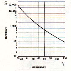 Diagram courtesy of Audi of America NOTE: If the sensor fails the ECU will use a substitute value that is based on the air temp sensor signal. If the air temperature is greater than 0C, (32F), the substitute value for the coolant temp will be 80C (176F). If the air temp is below 0C (32F), the substitute value is the intake air temperature for three minutes and then switched to 80C (176F) [1]. 1991 200TQ 20V and 1992-95 S4/S6,: It is also helpful to verify the wiring from the ECU to the coolant temp sensor, by removing the ECU connector, and then by checking the resistance across the ECU pin 45 and 30 to measure the coolant temperature sensor resistance with it plugged into the connector at the cylinder head. Pin 30 is connected to the engine ground wires at the intake manifold. CHECK THE WIRING CONNECTORS: NOTE: In one instance I found a problem where one of the electrical terminals at this connector had pulled out and was intermittent, which caused some weird idle behavior when warming up. In another instance on a 1991 200TQ 20V, I ran across a car that had the electrical connectors from the heater valve temp sensor, the carbon canister valve, and the engine coolant temp sensor mixed up and connected to the wrong item. The color of the connectors may not match the color of the temperature sensor or component they connect to. I recommend you pull back the rubber boot on each connector and verify the wire color code to make sure the sensors are connected to the right wiring connector. For the 1991 200TQ 20V (3B engine) The Engine Coolant temp sensor connector should have two wires, one Gray with brown stripe, one Green with black stripe. The Carbon Canister solenoid connector has two wires, a Red colored wire and a White with red stripe wire. The heater valve coolant temp sensor electrical connector should have two wires, a Yellow and red stripe wire and a Brown with black stripe wire. 20V ECU system information index References: [1] Audi of America, Technical service training publication: "The New 20V Turbo Engine for the Audi 200 Quattro-publication All rights reserved. Copyright © SJM Autotechnik™ , all rights reserved Return to Troubleshooting Tips page. Return to SJM Autotechnik™ main page. |
| About Us Privacy Policy Terms of Use Links Customer Service Safety Information Home |