

|
20V Motronic ECU System, Technical Tips, 1991 200TQ and 1992-95 S4/S6 with 20V Engine: AIR TEMP SENSOR The air temp sensor is used by the ECU to adjust ignition timing, knock regulation and boost pressure control [1]. As the intake air temperature increases beyond a certain set point, the boost pressure is reduced to prevent detonation. The timing will be retarded as well. The air temp sensor can have poor wiring connections at the sensor or the sensor tip welded connection can be intermittent on these cars as well. You may need to use a magnifying glass to see a problem with a cracked connection at the tip of this sensor. The sensor is a temperature variable resistor or thermistor. 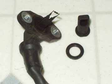
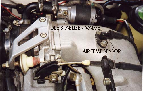 1991 200TQ 20V 5 cylinder Turbo engine Location 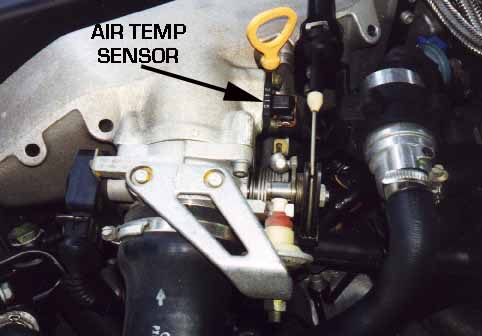 1992-95 S4/S6 with 20V 5 Cylinder Turbo Engine It is a good idea to pull back the rubber boot around the wiring connection and check for frayed or broken wires. These wires are spot welded or soldered on by the factory. Small crimp on terminals can be used, but spot welding or soldering makes for a better connection. The 1992-95 S4/S6 and the Factory replacement air temp sensors use a gold plated 2 terminal connector instead of being wired directly. If you are replacing the sensor on the 1991 200TQ 20V, a new connector housing is required along with gold plated terminals that are crimped onto the existing wiring after cutting off the old sensor. A rubber boot may also be needed for the connector. This sensor has a rubber boot to keep water/dirt out. On vehicles that have the sensor hard wired into the harness, if you want to measure the resistance of this air temp sensor, you must first isolate the sensor from the ECU circuitry. On the 1992-95 S4/S6, you can simply unplug the electrical connector at the sensor and measure the resistance directly across the air temp sensor terminals. On the 1991 200TQ 20V, you need to remove the ECU connector from the ECU. With the ECU connector removed, the resistance measured across the air temp sensor pins or across the appropriate ECU connector pins # 44 and # 2 to check the wiring between the ECU and the resistance of the sensor. You can also measure across terminals #44 and #30 as ECU terminals # 30 and # 2 are connected via a welded connection inside the ECU harness. The resistance should be approximately 500 ohms at 25C (70F). The resistance measured doesn't need to be "exactly" as shown, it just needs to be close to the value shown. Here is a graph of the sensor resistance versus temperature. 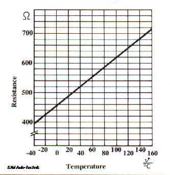 Diagram courtesy of Audi of America NOTE: If the air temp sensor fails, the ignition timing is retarded and a replacement air temp value of 40C is used for boost regulation [1]. Return to 20V ECU System information index References: [1] Audi of America, Technical service training publication: "The New 20V Turbo Engine for the Audi 200 Quattro-publication All rights reserved. Copyright © SJM Autotechnik™ , all rights reserved Return to Troubleshooting Tips page. Return to SJM Autotechnik™ main page. |
| About Us Privacy Policy Terms of Use Links Customer Service Safety Information Home |