|
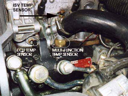
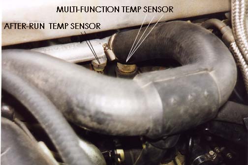
ECU System, Throttle Switch and Multi-Function Temp Sensor Tests
The throttle switch assembly has two switches inside which provide idle and full throttle information to the ECU. This throttle switch typically gets intermittent in operation because it develops poor internal solder connections over time from the thermal cycling (hot/cold) of the engine. It is also a good idea to visually inspect the wiring harness wiring and connector pins underneath the rubber boot at the connector on this throttle switch. Several folks have reported finding the wiring frayed and damaged which caused intermittent connections to the ECU. If your car still has the original style throttle switch, (see photo below) I can guarantee that it is going to be defective and have intermittent operation. 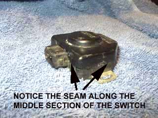 I have taken apart over 20 of these old style throttle switches and every one I looked at had cracked solder joints at the idle switch and the full throttle switch connections. These cracked joints which caused intermittent operation. Keep in mind that there will NOT be any stored ECU fault codes, codes 2123 (full throttle), or 2121 (idle switch) when the throttle switch fails in an open circuit non operational condition. Only a shorted idle or full throttle switch or shorted wiring will cause these fault codes to be stored. Intermittent operation of the idle portion of the throttle switch will cause some strange intermittent high idle (1500-2500 RPM) conditions that come and go and this can cause surging during deceleration. Intermittent operation of the full throttle switch inside this throttle switch can cause low boost problems as the ECU controlled Waste Gate Solenoid Operation will not occur. The replacement throttle switch has an improved design of the internal crimped connections. It carries the same Bosch part number as the original design as it is functionally the same but has a square body and a seam at the top of the switch as shown here. 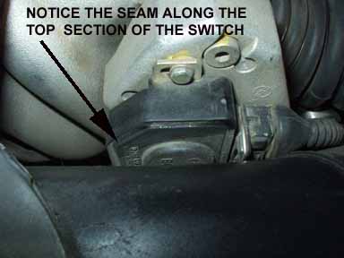 NOTE:If your idle speed is doing strange things, you can also have problems with the Idle Stabilizer Valve (ISV), the Idle Stabilizer Control Unit or the engine temperature sensor for the Idle Stabilizer Control Unit. Go to CIS Fuel Injectionsection for details on checking out the Idle Stabilizer system. In some cases the ISV operation can be erratic and stick from oil and other gunk that builds up inside on the plunger. In some cases you can remove the ISV and use some carb cleaner spray to clean out the plunger. NOTE: The Multi-Function Temperature Sensor can also cause low boost problems. The wiring from the ECU to the throttle switch, and the function of the Multi-function Temp Sensor can be tested at the same time. Go to the Multi-Function Temp Sensor section below for details. As mentioned, a defective throttle switch (full throttle portion) can prevent the correct operation of the Waste Gate (WG) solenoid system that the ECU uses to add pressure on top of the waste gate diaphragm to adjust the turbo boost. Testing the idle portion of the Throttle Switch (New Style Switches). Remove the 3 Pin connector to this throttle switch by using your thumb to push on the wire release clip. Some early vehicles have a different wire release, and will require a small dental pick or screw driver to pry open the wire retainer to allow the connector to be pulled loose. 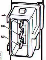 Use a Digital Multimeter (DMM) to probe the idle switch terminals for a good low resistance connection (less than 1 ohm resistance). Probe between the center (2) and the top terminal (1) on the throttle switch assembly with the throttle closed. NOTE: Many low cost DMM's don't measure low resistances very well. There is also the test lead resistance that can throw off your low resistance measurement as this resistance is usually 0.1 to 0.5 ohms. You should check the lead resistance of your DMM but touching the two lead tips together, and subtract this lead resistance from your measurement when you check the throttle switch idle and full throttle contacts. You should hear the idle portion of the throttle switch "click" as you open and close the throttle. If the idle switch contacts get shorted together even with the throttle open, the ECU won't allow Waste Gate Solenoid operation for boost control at wide open throttle operation. If you don't hear this clicking, you should check the adjustment of the switch at idle. You can do a basic adjustment of the throttle switch by connecting a Multimeter (DMM) across the two upper pins and measure the idle switch resistance. See procedure above for details. NOTE: The throttle should be closed when doing this adjustment. Sometimes carbon gets built up on the inside of the throttle plate and this prevents the throttle from fully closing. In other cases some bonehead has used the throttle plate stop screw to adjust the idle speed (WRONG) and this has screwed up the resting position of the throttle plate. Check the Bentley manual for specific throttle plate stop adjustment and idle switch adjustment if this has been altered. ADJUSTMENT PROCEDURE: Loosen the two 7mm bolts (Phillips screws) holding the switch to the throttle body and rotate the switch clockwise until it stops, the idle switch resistance should be very high indicating the switch is open, then slowly rotate the switch counter-clockwise until you hear the switch "click" and you read less than 1 ohms resistance indicating the idle switch is closed and working. You should continue to rotate the switch counter-clockwise a very slight amount just after you see the resistance drop down to <1.0 ohm and then tighten the screws on the throttle switch. Now double check the operation of the switch by opening the throttle and allowing the throttle to close on its own. Every time the throttle closes on its own, you want to make sure the idle switch is closing and you see the resistance drop down below 1 ohm. The Bentley procedure for adjusting the throttle switch (idle portion), has you remove the entire throttle assembly, so that a 0.004 inch (0.1mm) feeler gauge can be inserted in-between the throttle stop to slightly open up the throttle while you adjust the switch position as indicated above. That is why you need to continue to rotate the switch counterclockwise a slight amount, after seeing the resistance drop below 1.0 ohm if you are adjusting the throttle switch with the throttle body assembly on the engine. Testing the Wide Open Throttle (WOT) portion of the Throttle Switch. After checking the idle portion of the throttle switch, use the DMM to check for a good low resistance connection (less than 1 ohm) between the center (2) and bottom terminal (3) with the throttle opened fully (ENGINE NOT RUNNING). The Wide Open Throttle portion of this switch should make contact after the throttle is opened all the way. You will NOT hear any clicking noise when the WOT portion of the throttle switch is making contact. NEW VERSUS OLD STYLE THROTTLE SWITCH To repeat, the new style switch uses an improved crimp and soldered connection on the internal terminals, whereas the early design had the terminals butted up against each other and then they were soldered. This was mechanically weaker when compared to the new design. The new style Bosch Throttle switch looks different when compared to the original design. The new throttle switch plastic cover has thick black epoxy sealing the top edge, whereas the early design throttle switch cover was split on the side in the middle and had four plastic tangs that extended into four slots. The early design used a thin coating of plastic glue to seal the cover and can be cut open with a razor knife. Make sure you test the operation of the new replacement throttle switch, as I have found some new throttle switches that were defective from the factory. Here is what the original early design throttle switch looks like on the inside, with the cover removed. 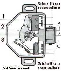 Diagram courtesy of Robert Bosch Corporation (1) points to the idle micro-switch, this switch should have an audible click when the lever pushes against it. I don't recommend taking this micro-switch apart unless you are training to be a brain surgeon. Some Electronic supply stores may have a replacement micro-switch available. (2) points to the throttle shaft cam that actuates the idle and full throttle switches. (3 )points to the full throttle portion of this throttle switch assembly. This full throttle switch is supposed to make contact at 2/3 or greater throttle openings. If you are the curious or adventurous type or have some time on your hands, the throttle switch can be removed from the throttle body and the internal switch connections can be repaired. Remove the two 7mm bolts and slide the throttle switch off the throttle shaft. The plastic cover on the throttle switch can be cut off with care using a sharp razor knife, and pried open using a small screwdriver. (BE VERY CAREFUL USING THE RAZOR KNIFE). In some cases a small hammer can be used to tap the side of the throttle switch and break loose the glue holding the cover on. The internal connections can be looked at with a magnifying glass to see the cracks that always occur at the solder joints. You can also try repairing the solder connections by re-soldering them if money is tight. You may want to use solder wick to remove the old solder and then wrap some fine wire around the joint to strengthen it. Then solder using a good rosin core solder or for more strength, some solder with silver content will also work. Clean the WOT contacts with contact cleaner or some fine sandpaper. Silicone sealer can be used to glue the cover back on the switch. NOTE: THIS BEARS REPEATING It is important to understand that testing the resistance of this switch with a DMM is a good idea, and is good for the experience, but very often with the old style throttle switches, the test will show a low resistance and it will appear to be working ok at idle or full throttle AT THAT MOMENT. But...... in 99% of the cases, with a high mileage original switch, the idle or full throttle switch will go open circuit or will have increased resistance (over 1 ohm) from the cracked internal solder joints at a later time, when subjected to vibration and heat that occurs while driving the car. Sometimes the probing action with the DMM during testing, moves the terminal connection enough to reestablish the cracked internal solder connection inside the switch. If you get different resistance readings that seem to change each time you probe and test the switch, you should suspect the internal connections are cracked and are causing these changing resistance values.
|
| About Us Privacy Policy Terms of Use Links Customer Service Safety Information Home |