Engine Control Unit (ECU) Coolant Temperature Sensor
Idle Stabilizer Valve (ISV) System Coolant Temperature Sensor
ECU Air Temperature Sensor
1986-90 5000/200TQ
ECU COOLANT TEMP SENSOR and ISV COOLANT TEMP SENSOR
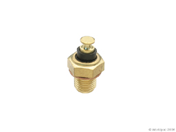
The ECU coolant temp sensor (single wire version) that is screwed into
the cylinder head just slightly below and forward of cylinder #1 spark
plug should be tested if you are having any mixture problems. If you
have a broken wire or poor connection between the ECU and this sensor,
the ECU will think the engine is cold and will run rich.
NOTE: The Idle Stabilizer Valve (ISV) control system uses a coolant
temperature sensor that is screwed into the top of the coolant outlet
that is mounted on the cylinder head. This ISV temperature sensor has
the same part number as was used for the ECU coolant temperature sensor.
Two different systems, two different sensor locations, but they use
the same part numbered sensor to measure coolant temperature. The test
procedure for the ECU and ISV coolant temperature sensor is the same.
To test, you disconnect the single wire terminal at the sensor and measure
the resistance from the sensor connection to the cylinder head (ground).
Check continuity between pin 10 on the ECU and the blue wire connected
to this sensor. Sometimes the BL/G (Blue wire with Green stripe) wire
from the idle stabilizer temp sensor nearby gets incorrectly connected
to the engine coolant temp sensor.
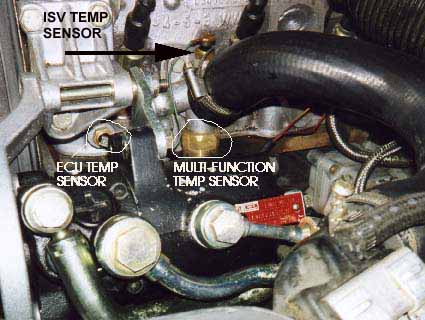
See photo below for location info. In some cases the sensor can be intermittent
when the engine warms up, which will cause some strange rich running
conditions because the ECU will occasionally think the engine temp is
much colder than it really is.
Although it is not stated anywhere in the Bentley service information,
the ECU will operate the cold start valve briefly as you begin accelerating
when the engine is cold with a coolant temp below 150F. If the sensor
is intermittent, the ECU may activate this cold start valve when the
engine is warm and this will make the engine run very rough.
With the single wire removed, the resistance should be tested between
the sensor terminal and the cylinder head (engine ground). The resistance
should be approximately 80 ohms with the coolant temp around 212F, (100C),
approximately 130 ohms with the coolant temp at 176 degrees F (80C),
approximately 1000 ohms at 68F (20C), and approximately 6000 ohms at
-4F (-20C).
This sensor is a Negative Temperature Coefficient (NTC) type sensor,
that has decreasing resistance with increasing temperature.
-
AIR TEMP SENSOR
The air temp sensor that the ECU uses to control boost and timing
can have poor connections and work intermittently. Sometimes the terminals
get broken off during other service work on the engine.
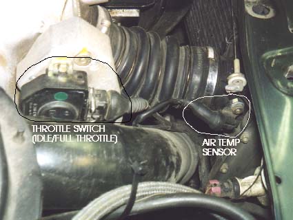
Here is a photo showing the location of the air temp sensor which
is mounted on the intercooler outlet.
It is a good idea to check the air temp sensor connections even if
no fault codes are recorded by the ECU. I have found several cases
where the wires on the air temp sensor were broken off and the throttle
switch was defective, but NO fault codes were recorded by the ECU.
Pull back the rubber boot around the wiring connection and cut off
the heat shrink tubing off the connection and visually check for frayed
or broken wires.
Often times the outer wire insulation will look ok, but the wire is
broken internally.
NOTE: If the ECU senses the air temp sensor or wiring are defective,
it will still operate the Waste Gate Solenoid system with a reduced
duty cycle value. This reduced duty cycle driving the Waste Gate solenoid
will limit the amount of pressure added to the upper Waste Gate Chamber.
In other words, the system will appear to be functioning normally,
but the boost will still be lower than expected. The air temp sensor
connection terminals are spot welded on by the factory.
Small crimp on terminals (0.110 inch size) can be used to repair this
connection along with soldering the terminals to the sensor. Factory
replacement air temp sensors have gold plated terminals and gold plated
connector terminals along with a new connector housing. This sensor
is located on the intercooler exit and has a rubber boot to keep water/dirt
out.
When you check the resistance of this air temp sensor, you should
first remove the ECU connector to isolate the air temp sensor from
the ECU circuitry and measure the resistance across the ECU connector
terminals.
Next, you can reconnect the ECU connector and recheck the resistance
across the ECU connector terminals to see if the resistance value
has changed now that the air temp sensor is connected to the internal
ECU circuitry.
This last test will verify that the ECU connector terminals for the
air temp sensor are ok. You can also measure the air temp sensor resistance
across the sensor itself, if one of the wires has already broken off,
before you make the repair.
The resistance measured across the air temp sensor should be around
500 ohms at 25C (70F). If you have intermittent boost problems and
the sensor wiring tests ok, you may want to remove the air temp sensor
from the intercooler and inspect the sensor tip area with a magnifying
glass and look for a cracked connection where the resistive sensor
element is spot welded to the two terminals.
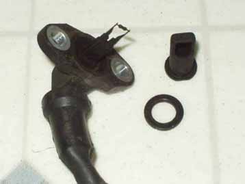
After removing the O-Ring seal, the plastic sheath/cover can be pulled
off the tip of the air temp sensor for better access. In a few cases,
I have found the sensor to work one minute, then go open circuit intermittently
at other times, and this was due to cracked spot weld(s) at the tip
of the sensor where the resistive element is attached.
Here is a graph of the sensor resistance versus temperature. This
sensor is a Positive Temperature Coefficient (PTC) type sensor, that
has increasing resistance with increasing temperature .
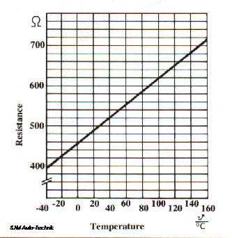
Graph courtesy of Audi of America, Technical Service Training.
Go to ECU System Technical Tips
Copyright © SJM Autotechnik™ , all rights reserved
Return to Troubleshooting Tips page.
Return to SJM Autotechnik™ main
page.